4mA
4.8mA
5.6mA
6.4mA
7.2mA
8.0mA
8.8mA
9.6mA
10.4mA
11.2mA
12.0mA
12.8mA
13.6mA
14.4mA
15.2mA
16.0mA
16.8mA
17.6mA
18.4mA
19.2mA
-20mA
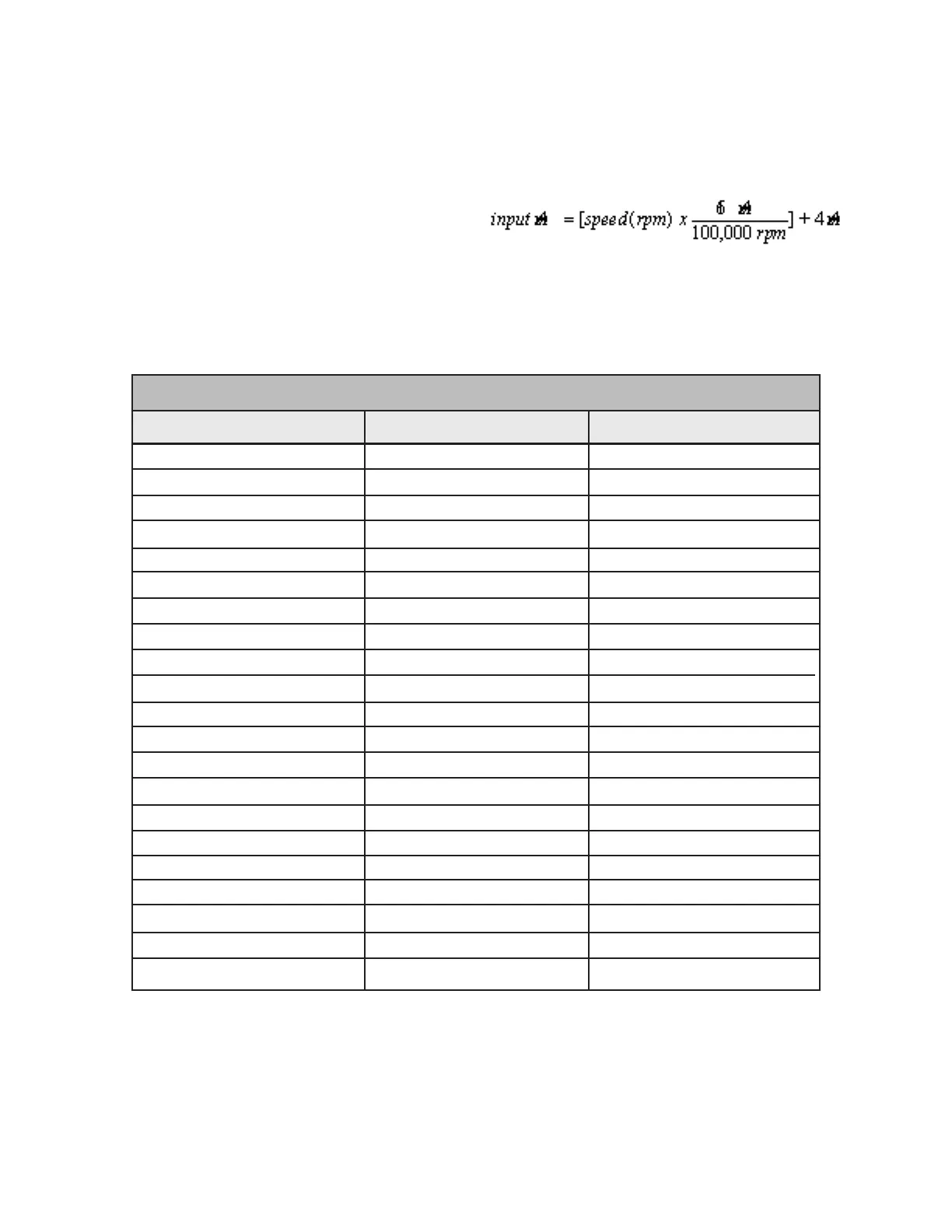
TABLE 3 - INPUT SIGNALS FOR GIVEN SPEEDS
0
5,000
10,000
15,000
20,000
25,000
30,000
35,000
40,000
45,000
50,000
55,000
60,000
65,000
70,000
75,000
80,000
85,000
90,000
95,000
100,000
Desired Speed (rpm)
4-20mADC Input Signal
0 V
0.5 V
1.0 V
1.5 V
2.0 V
2.5 V
3.0 V
3.5 V
4.0 V
4.5 V
5.0 V
5.5 V
6.0 V
6.5 V
7.0 V
7.5 V
8.0 V
8.5 V
9.0 V
9.5 V
10.0 V
0-10VDC Input Signal
Inputs
Analog Speed Setpoint Inputs
Analog speed setpoint inputs are available for
rotators 1 through 6 at breakout terminals J2-A1
through J2-A6. Using dip switch 6 of SW1 on
the Control Card, these inputs can all be set so a
0-10VDC or 4-20mA input signal gives 0-100,000
rpm rotator speed. See "Dip Switch Settings" later
in this section.
Table 3 shows 0-10VDC and 4-20mADC input
signals for speeds from 0 to 100,000 rpm in steps
of 5,000 rpm.
For 4-20mA input signals, the following equation
can be used to determine the mA input signal
corresponding to a given speed: