6
4. WIRING SYSTEM
1. The device is equipped with the protective PE cable.
2. Before connecting the device to the power supply, check the compatibility of the mains
voltage with the device supplying voltage (data on the plate).
3. Connecting the device to the mains socket should be made so that the plug of the
connecting cable is visible and easily accessible for the service.
4. The device should be connected to a separate, properly made electrical circuit protected
by a fuse no greater than 10 A with a B-characteristic, ended with a socket with a protective
pin.
5. The device may be started only after confirming the effectiveness of the shock protection
with the results of measurements carried out in accordance with the applicable regulations.
6. Before carrying out any maintenance or cleaning, turn off the device with the switch and
then remove the plug from the mains socket.
7. The device is started after connecting the plug to the mains socket, and then by turning
on the switch. The backlight of the switch indicates that the device has been turned on.
8. Any repair of electrical installation and replacement of the connection cable (only into
original one available from the manufacturer) may be carried out by an authorized
electrician only.
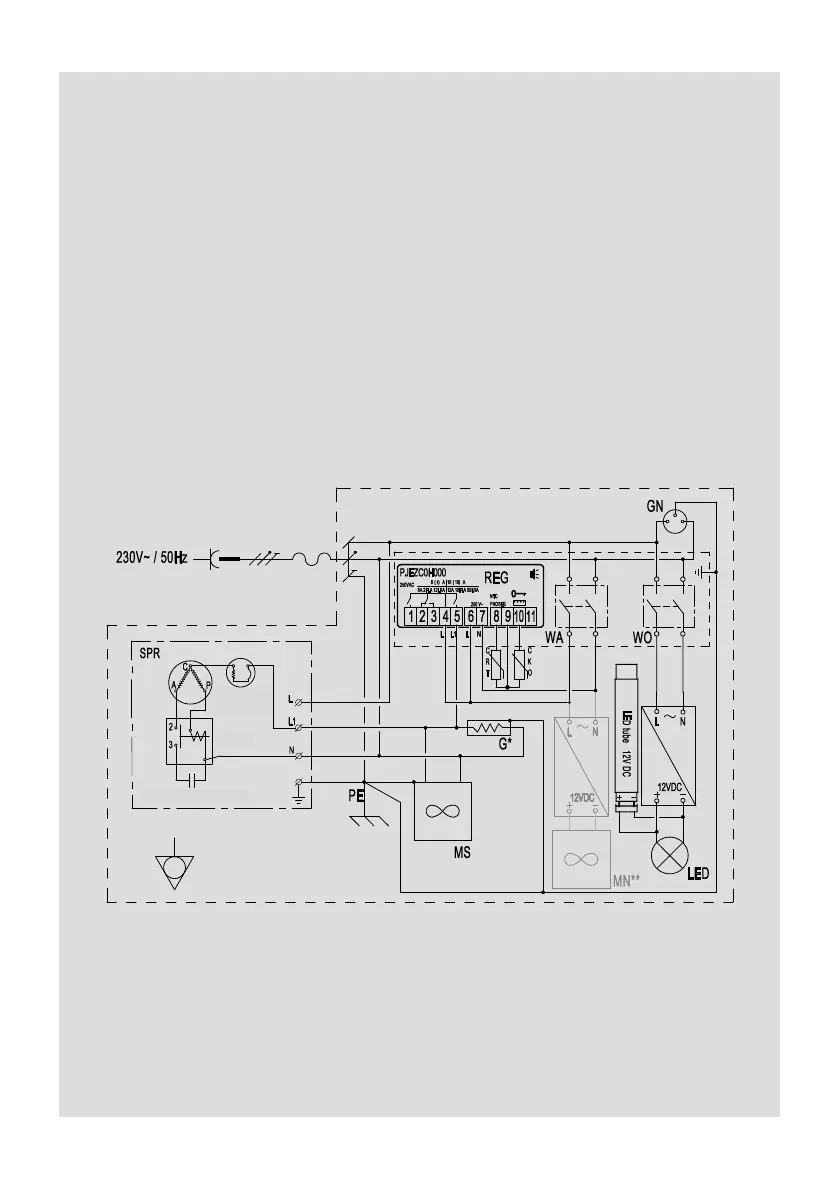
5. WIRING SYSTEM DIAGRAM
CKO – defrost ending sensor REG – electronic temperature regulator
CRT – electronic temperature regulator sensor SPR – compressor
G – PTC heater WA – aggregate switch
GN – electric socket WO – lighting switch
MS – condenser fan MN – evaporator fan
* - additional equipment
** - applicable to refrigerated counter and module L-F/NW