EasyManuals Logo

Rational UltraVent User Manual

Rational UltraVent
32 pages
To Next Page IconTo Next Page
To Previous Page IconTo Previous Page
Page #10 background imageLoading...
Page #10 background image
UV-USA SCC_WE, CM_P V04, 02/2013
10
17
18
19
15
6
7
16
6
5
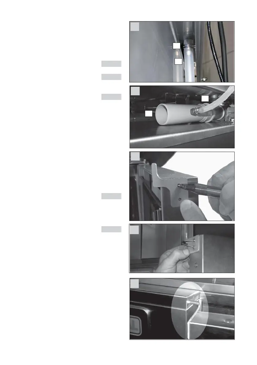
2.5 Condensation water
- At the rear side of the Ultravent there is a drain
connection for the condensated water inside the
hood.
- Connect the silicone hose (pic. 1 pos 6) with the
hose
clips (pic. 1 pos. 7) to the drain tube
pic 15
- Put the drain pipe (pic 1 pos. 5) to the unit’s
drain pic. 16
- Shorten the silicone hose (pic. 1 pos 6) to the
desired length and push it over the connection
piece of the drain pipe (pic. 1 pos. 5) pic. 16
- Ensure there are no kinks or sags in the hose.
Cut length to fit depending on unit size
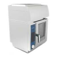
3. Installation of the lock plate.
a) Use lock plate (pic 2 item 12) as a template.
Hold it to the top edge of the door and mark
the two holes. pic. 17
b) Drill two holes (3,2 mm approx. 1/8”) at the
marked positions into the door frame
c) Hold lock plate (pic 2 item 12) to top edge of the
door and fix the plate with the rivets (item 13)
pic. 18/19

Questions and Answers:

Question and Answer IconNeed help?

Do you have a question about the Rational UltraVent and is the answer not in the manual?

Rational UltraVent Specifications

General IconGeneral
MaterialStainless Steel
CompatibilityiCombi Pro / iCombi Classic
CategoryVentilation Hood
Airflow CapacityVaries depending on iCombi Pro/Classic model
Noise LevelVaries depending on iCombi Pro/Classic model
Power ConsumptionVaries depending on iCombi Pro/Classic model
VoltageVaries depending on iCombi Pro/Classic model
DimensionsVaries depending on iCombi Pro/Classic model
WeightVaries depending on iCombi Pro/Classic model
TypeCondensation hood with condensation technology

Related product manuals