UV-USA SCC_WE, CM_P V04, 02/2013
8
12
Fix with self adhesive
cable clips
9
Term.: 1/2
Control cable to
pcb X23 (W26)
10
K8
X18
K2
K1
K5
X19
X75
K4
K3
K10
K9
G3
+
X23
X20
F1
F2
X21
K6
K7
K11
K12
X14
+
X13
LED V68
F2
2AT
F1
2AT
From Ultravent (term. 1/2)
X26
X27
X8
X11
X13
X14
X23
X21
X18X19X20
F1
From Ultravent (term. 1/2)
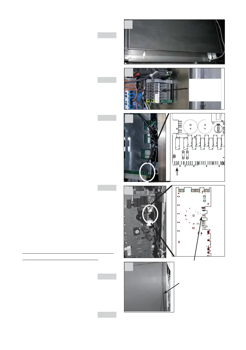
2.2 Fitting the control cable
- On the rear of the UltraVent® there is a power
box; open it by loosing the screws. pic. 8
- For connection run cables through correspon-
ding cable glands into power box.
- The control cable W26 (pic. 1 item 3) is included
in the Ultravent kit. Connect this cable as
follows: pic. 9
- on SCC_WE-units: pic. 10
Connect control cable W26 to terminal X23 of
the cpu pcb
- on CM_P-units: pic. 11
Connect the control cable W 26 to X23 of the
operator pcb
- Run the cable back out through the cable gland
and up the back of the Combi-Steamer to the
power box of the Ultravent®.
- The control cable has a green, a white and
brown wire.
- For the connection of the Ultravent only the
green and the white wire are needed.
Connect the green wire to terminal 1 and the
white wire to terminal 2 of the power box
Ultravent pic 9
Insulate the brown wire
- The cable can be affixed to the back of the appli-
ance with the self-adhesive cable clips supplied
(pic1 item 4) pic. 12
8
11