Wuhan Raycus Fiber Laser Technologies CO., Ltd.
RFL-P100QA Pulsed Fiber Laser User’s Guide V2.1
5
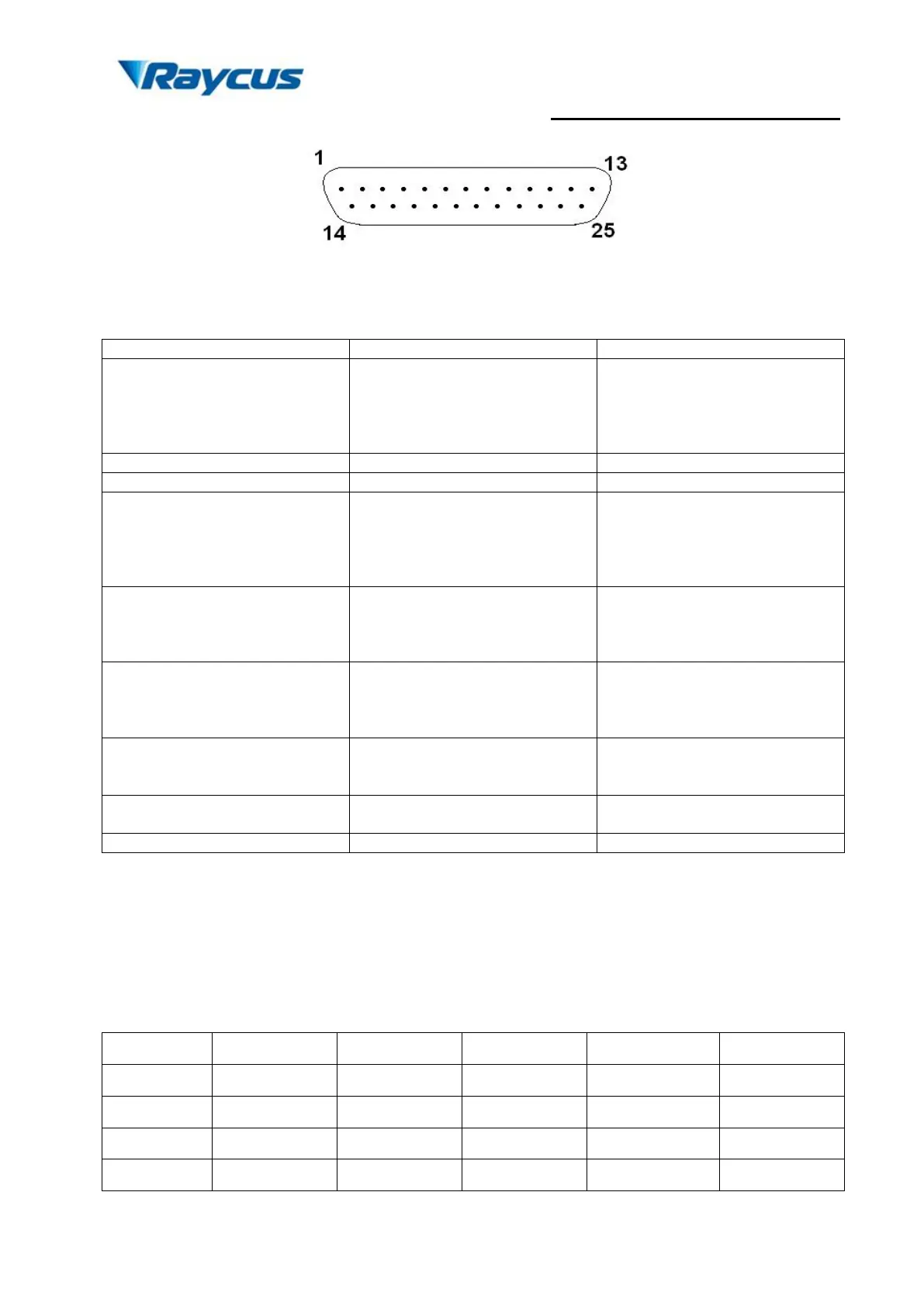
Figure 5 Connect port of controller
Table 3 Definition of connect ports of controller
8 bit Parallel port; D0 is minimum
bit and D7 is maximum bit;
Range: 0-255 (hexadecimal:
0X00-0XFF); 0 is minimum power
and 255 is maximum power.
see alarm codes in the table below
+5 VDC power supply input for
independent operation of the guide
laser and PCB.
Maximum current consumption is
0.1 A.
Emission Enable (EE) signal.
HIGH: Emission Enable
LOW or disconnected: Emission
Disable
Emission Modulation (EM) input.
HIGH (>3 V): Emission ON
LOW or disconnected (<1 V):
Emission OFF
Pulse Repetition Rate
(Synchronization) input, square
wave.
Guide Laser (red diode) ON/OFF
input.
a) The pump current of diode laser and the laser output power are controlled by setting the
value of PIN1-PIN8 (TTL level). PIN1-PIN8 can be set from 0
~
255
,
corresponding to the
laser output power from 0~100% (the actual laser power may not be strictly linear with the
setting value). The relationship between PIN value and output power is shown in Table 4:
Table 4 Definition of power control PIN value