.
User’s guide Ytterbium Pulsed Fiber Laser RFL-P20QB~P30QB Ver.: 2.0
6
(1) The pump current of diode laser and the laser output power are controlled by setting the
value of PIN1-PIN8 (TTL level). PIN1-PIN8 can be set from 0~255,corresponding to the
laser output power from 0~100%( the actual laser power may not be strictly linear with the
setting value). The relationship between PIN value and output power is shown in Table 4:
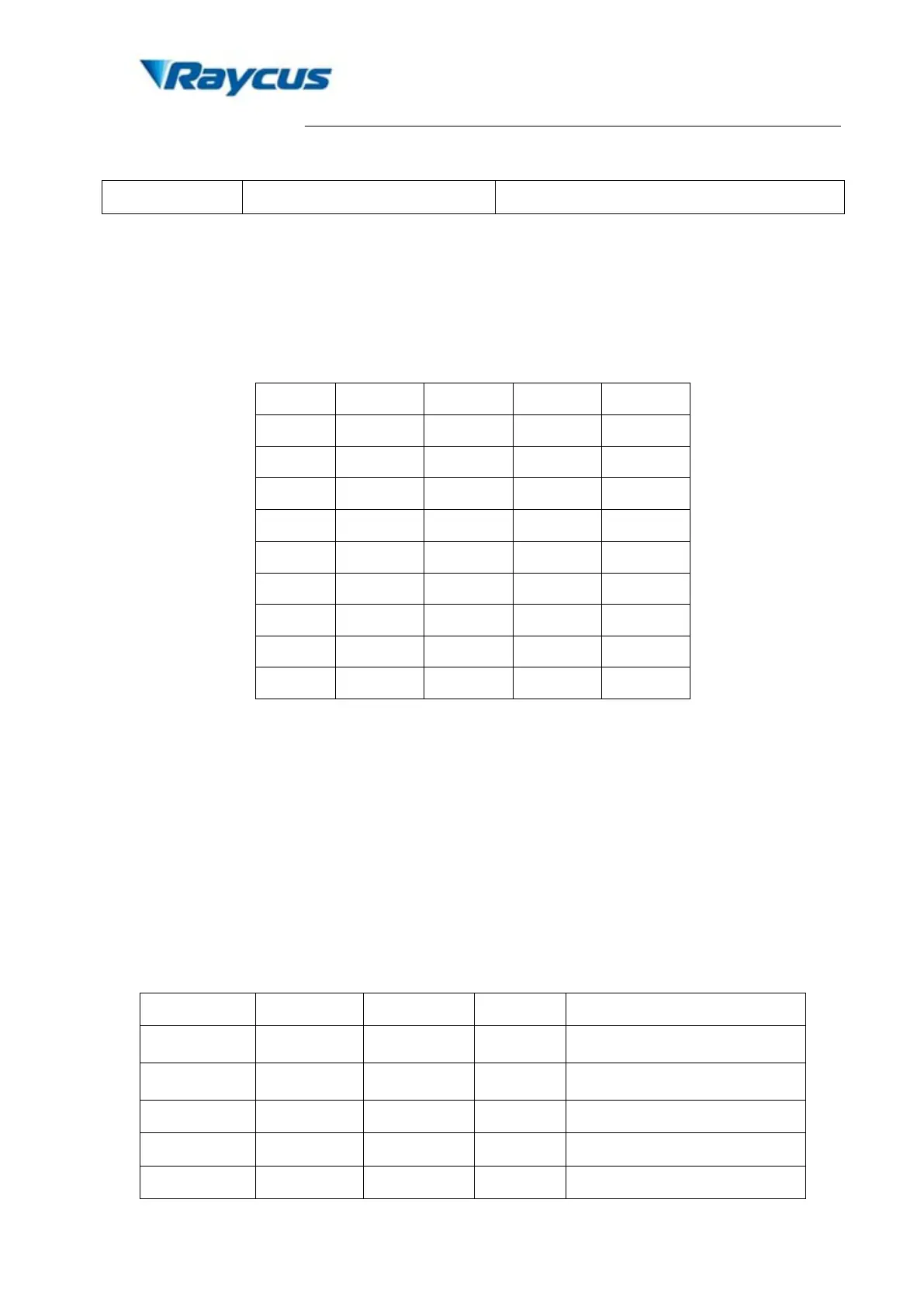
Table 5. Definition of power control PIN value.
(2) PIN 17 is the external 5V input, providing power supply for alarm signal: input current>
20mA.
(3) The external input signals (Pin 1-8, 18-20, 22) are connected to the optical coupler inside the
system. Input voltage 3V-5V are defined as digital High, below 1V are defined as digital
Low.
(4) Alarm setting: Pins 11, 12, 16 and 21 are the alarm and status outputs which driven by +5V
power from Pin 17. Pin 12 is reserved (always be high). These pins indicate the following
device states.
Table 6. Definition of alarm states.
×
Low Low Low Temperature alarm
×
Low Low High Normal
×
×
×
 Loading...