.
User’s guide Ytterbium Pulsed Fiber Laser RFL-P20QB~P30QB Ver.: 2.0
5
3. Control Interface
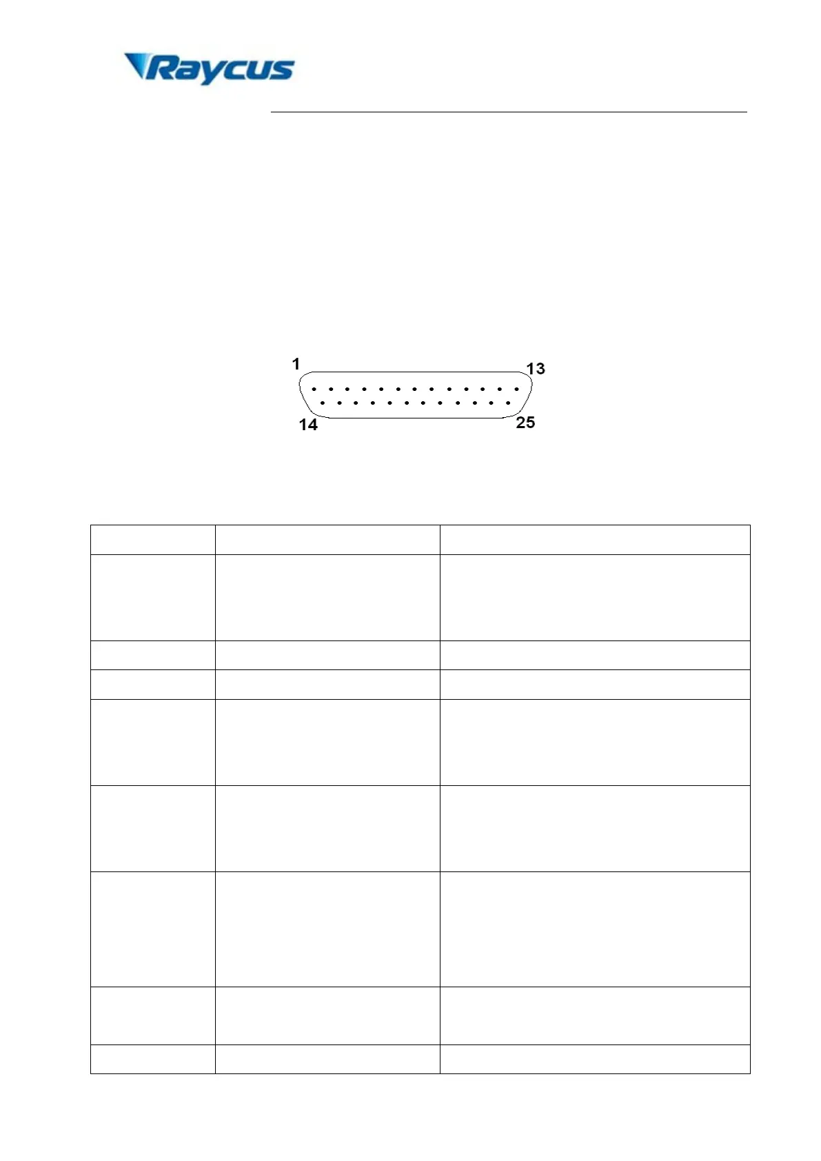
There are DB9 and DB25 interfaces at the rear of the laser. The DB9 is a RS232 interface
only used for debugging, no needs to connect. And DB25 is the joint interface connecting control
system to the laser system, please make sure the connection is reliable before operation. Feet of
the DB25 are defined as follows in Fig. 5.
Figure 5. Connect port of controller.
Table 4 Definition of connect ports of controller.
1-8 (D0-D7)
Power Setting
8 bits parallel port, D0 is minimum bit and
D7 is maximum bit;
Range: 0-255 (hexadecimal: 0x00-0xFF);
See alarm codes in Table 4
17 VCC
+5VDC power supply input for independent
operation of the guide laser and PCB,
Maximum current consumption is 0.1A.
18 EE
Emission Enable (EE) signal.
HIGH: Emission Enable;
LOW or disconnected: Emission Disable.
19 EM
Emission Modulation (EM) input.
HIGH (>3V): Emission ON;
LOW or disconnected (<1V): Emission
OFF.
20 Sync
Pulse Repetition Rate (Synchronization)
input, square wave.
Guide Laser (red diode) ON/OFF input.