.
User’s guide Ytterbium Pulsed Fiber Laser RFL-P20QB~P30QB Ver.: 2.0
4
device and output isolator must be packed with suitable soft materials in case of
damaging due to vibration during the transportation.
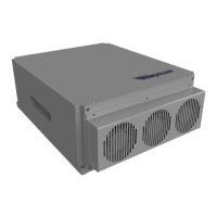
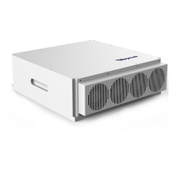
(2) Fix the laser device steady on the holder and ensure good ventilation.
(3) The power connector of this high performance small volume laser device is DB7 dual
power supply. Connect the power line to the 24V DC power supply and ensure
sufficient output power. Notice the polarity of the power line.
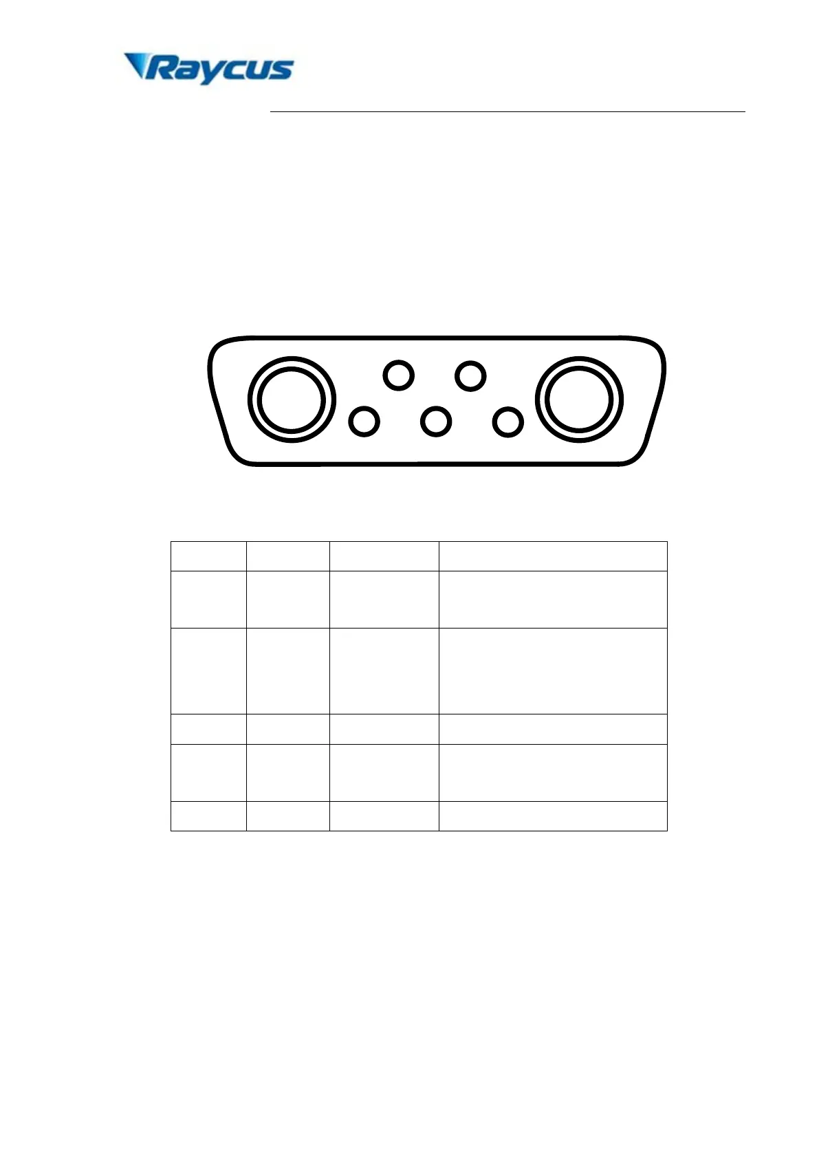
Figure 3. Schematic of DB7 power supply connector.
Table 3. Definition of small volume laser power connector.
A1 P24V+ Red
24 V laser driver power supply
positive input
A2 P24V- Black
24 V power supply negative
input for both laser driver
and control board
2 C24V+ Red
supply positive input
(4) Pin A1 & A2 are the positive and negative power line connector to the control board.
Pin 2 & A2 are the positive and negative power line connector to the laser driver.
During the operation, all the power connectors must be correctly connected, or laser
wouldn’t operate. Depending on the specific requirements in actual operation, the
control board and laser drive can be powered together or separately.
(5) During the operation, disconnection of any connect wire will lead the disable of laser
emission
(6) Make sure the control connector of external controller is compatible with the laser
device. Fix the control wire steady onto the laser control connector.