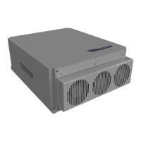
User’s guide Ytterbium Pulsed Fiber Laser RFL-P10Q/P20Q/ P30Q/ P20QE/P50QB Ver.: 2.0
6 / 9
1) The pump current of diode laser and the laser output power are controlled by setting the
value of PIN1-PIN8 (TTL level). PIN1-PIN8 can be set from 0~255,corresponding to the
laser output power from 0~100% (the actual laser power may not be strictly linear with the
setting value). The relationship between PIN value and output power is shown in Table 4:
Table 4 Definition of power control PIN value
PIN 2 0 0 0 0 1
PIN 7 0 1 1 1 1
2) Alarms status: Pins 11, 12, 16 and 21 are the alarm and status outputs. Pin 12 is reserved
(always be high). These pins indicate the following device states.
Table 5 Definition of alarm status.
×
Low Low Low Temperature alarm
×
×
×
×
×
×
×
3) PIN 10、PIN 13 to PIN 15、PIN 24 are all digital GND.
4) PIN 20 is the pulse repeating rate signal (PRR, TTL level). If the PRR need to be changed
during the work, it must be changed 5ms earlier than the EM signal turning into high.

 Loading...