Wuhan Raycus Fiber Laser Technologies CO., Ltd.
20QS/30QS Pulsed Fiber Laser User’s Guide V1
6
defined as digital Low. The input current should be above 2mA.
d) Alarms status: Pins 11, 12, 16 and 21 are the alarm and status outputs which driven by
+5V power from PIN 17. PIN 12 is reserved (always be high). These pins indicate the
following device states.
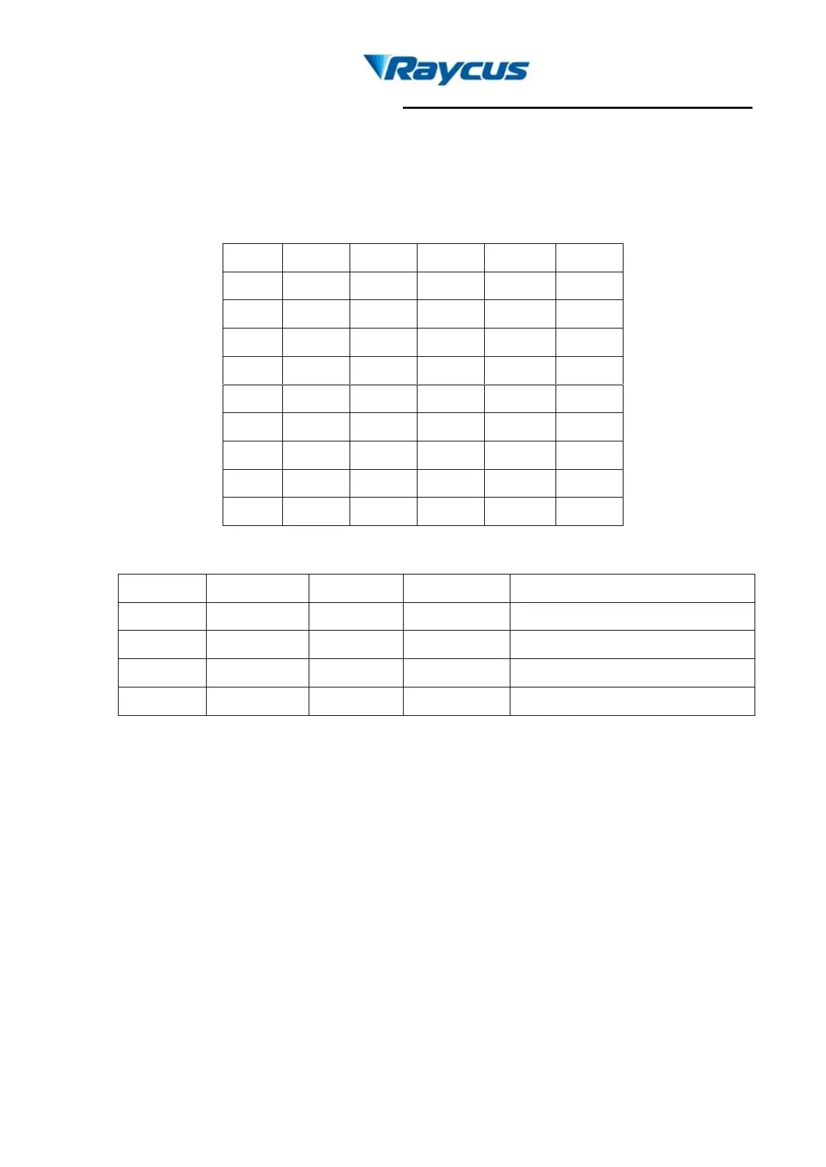
Table 4 Definition of power control PIN value
Table 5 Definition of alarm status.
e) PIN 10、13、14、15、24、25 are all digital GND.
f) PIN 20 is the pulse repeating rate signal(PRR, TTL level). If the PRR need to be
changed during the work, it must be changed 5ms earlier than the EM signal turning
into high.
g) PIN 22 is the guide laser (red diode)on/off signal. High level switch on the guide laser
while low level switch off the guide laser.
4. Operation Regulations
4.1 Pre-inspection
a) Make sure the device appearance is in good condition and the output fiber is
neitherexcessively bended nor broken.