Wuhan Raycus Fiber Laser Technologies CO., Ltd.
20QS/30QS Pulsed Fiber Laser User’s Guide V1
4
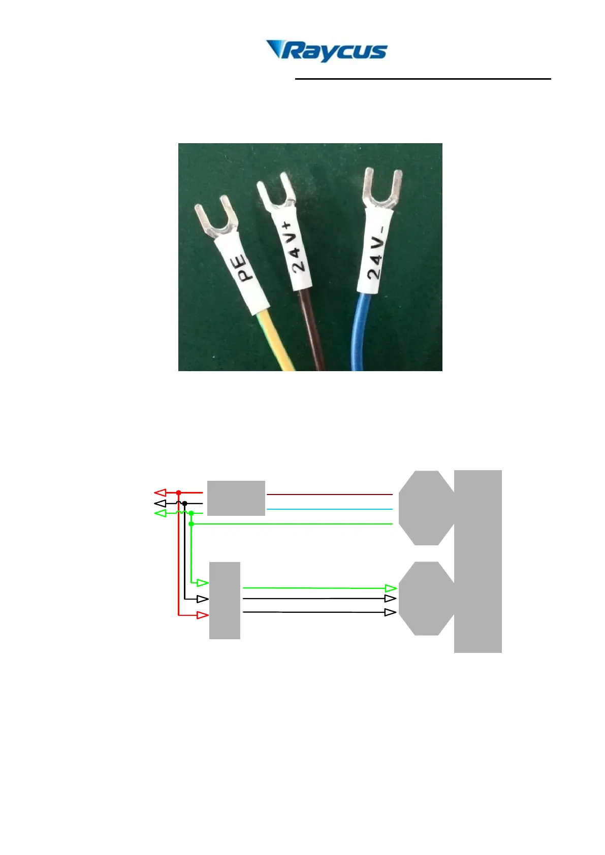
b) Connect the power line to 24VDC power and ensure enough DC output power.Keep it
clear to the polarity of the electric current: anode-brown; cathode-blue; PE-yellow and
green. The definition figure is shown in Fig. 3.
Figure 3. Definition of power line wires
c) Make sure that the interface of the external controllermatches the laser and the control
cable is well connected to the laser’s interface. The recommended electrical connection
is shown in Fig. 4.
User
’s
cont
rolle
r
DB25
Controller
interface
Power
supply
wire
Laser
Module
24V+(Brown)
L
N
GND
External GND
24V
power
supply
24V-(Blue)
Figure 4. Schematic of recommended electrical connection
d) The bending radius of the delivery fiber should not less than 15cm.
3. Control Interface
There are DB9 and DB25 interfaces at the rear of the laser. The DB9 is a RS232 interface
only used for debugging, no needs to connect. And DB25 is the joint interface connecting control