Do you have a question about the Raymarine 150 and is the answer not in the manual?
Read through the handbook to familiarize yourself with the autopilot system and its installation.
Gather the necessary tools and equipment required for installing the core pack components.
Verify that all components listed in the core pack parts diagram are present.
Determine appropriate mounting locations for the course computer and compass based on system requirements.
Follow guidelines to ensure optimum Electromagnetic Compatibility (EMC) performance during installation.
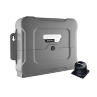
Choose a suitable vertical and flat bulkhead location below decks for the course computer.
Mount the course computer securely using provided screws and keyhole slots.
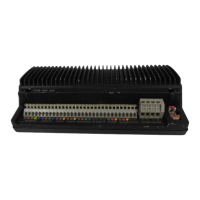
Unlock and remove the connector cover to access the course computer's terminals.
Connect the power supply cables to the course computer, ensuring correct size and connections.
Identify the best location for the fluxgate compass, considering pitch, roll, and magnetic interference.
Mount the fluxgate compass vertically, ensuring correct orientation and cable exit.
Route the compass cable and connect its cores to the FLUXGATE terminals on the course computer.
Install the rotary rudder position sensor, connecting it directly to the boat's tiller arm or quadrant.
Install the linear rudder position sensor on 'bullhorn' style hydraulic outboard steering systems.
Connect additional SeaTalk control units and SeaTalk equipment to the autopilot system.
Connect NMEA 0183 data equipment, such as GPS, to the autopilot system.
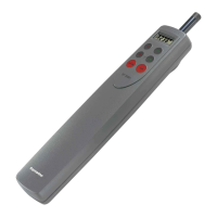
Connect optional components like GyroPlus yaw sensor and handheld remotes.
Perform initial setup and configuration of the autopilot system after installation.
| Brand | Raymarine |
|---|---|
| Model | 150 |
| Category | Autopilot System |
| Language | English |