T150/150G/T400/400G Course Computers
4 Type 150/150G/400/400G Course Computers Service Manual 83156-1
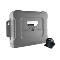
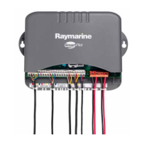
Type 150/400 Course Computers
Drive Output......................................................................................................28
Spool Valve Control..........................................................................................28
Clutch Drive ......................................................................................................28
Fluxgate Compass .............................................................................................28
Rate Gyro ..........................................................................................................29
External Gyro ....................................................................................................29
Internal Gyro .....................................................................................................29
Rudder Reference..............................................................................................29
NMEA Inputs ....................................................................................................30
NMEA Output...................................................................................................30
SeaTalk..............................................................................................................30
Microcontroller..................................................................................................30
Watchdog ..........................................................................................................31
Flash Memory Programming.............................................................................31
Non-Volatile Memory .......................................................................................31
Chapter 6: PCB Details ...............................................................................................................32
6.1. Inputs and outputs ..................................................................................................32
6.2. Circuit diagram and PCB layout ............................................................................33
6.3. PCB components....................................................................................................34
Type 150, 150G, 400 and 400G surface mount.................................................34
Type 150/150G conventional mount.................................................................37
Type 400/400G conventional mount.................................................................38
Chapter 7: Software Upgrade...................................................................................................39
7.1. Introduction............................................................................................................39
7.2. Minimum Requirements ........................................................................................39
7.3. Connecting the Course Computer to the PC ..........................................................39
7.4. Upgrade procedure.................................................................................................40
 Loading...