Do you have a question about the Raymarine SmartPilot S1 and is the answer not in the manual?
Overview of the Course Computer's function and components.
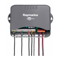
Diagram illustrating the components of the S1G Course Computer.
Essential precautions for handling sensitive components and preventing damage.
Requirements for using approved parts to maintain CE compliance.
Design standards for electromagnetic compatibility in marine environments.
Information on responsible disposal of electronic waste.
Disclaimer regarding the accuracy and potential changes in the manual.
Information on unit's lack of serviceable parts and replacement strategy.
Describes the purpose of the functional tests section.
Lists necessary items for performing functional tests.
Visual checks to perform before applying power.
Instructions for ensuring correct connection of the rate gyro.
General advice before commencing diagnostic tests.
Verifies correct voltage levels at specific test points.
Confirms correct display of compass heading and rudder bar.
Tests the voltage output of the rate gyro during rotation.
Checks the compass heading display during rotation.
Verifies rudder position display based on rudder reference input.
Tests clutch engagement in AUTO mode.
Tests clutch engagement in STANDBY mode.
Checks motor operation for forward and reverse drive.
Verifies data reception and transmission via NMEA.
Checks if calibration settings are stored correctly.
Lists the specific tools needed for disassembly and reassembly.
Provides step-by-step instructions for taking apart and putting together the unit.
Details past software versions and their changes.
Procedure for updating the Course Computer's firmware.
Lists specific technical updates issued for the product.
The SmartPilot S1 & S1G Course Computer is a core component of Raymarine autopilot systems, designed to process sensor information and steer a boat using a drive unit. This service manual provides detailed procedures for its maintenance, functional testing, and software upgrades.
The Course Computer acts as the central processing unit for the autopilot system. It receives data from various sensors, including the fluxgate compass, rate gyro, and rudder reference, to calculate and execute steering commands for the drive unit. The assembly consists of a plastic case housing a printed circuit board (PCB) which contains a microprocessor, electronic circuitry for drive unit control, a power amplifier for the drive motor, and a connector block for all inputs and outputs.
The Course Computer operates on a 12V DC power supply. It includes two fuses: a 15A fuse for power input and a 2A fuse for SeaTalk communications. The PCB features specific voltage test points for diagnostic purposes: +5V-DIG (4.9V-5.1V), HD-PWR (11.95V-12.05V), and PWR-OV (0V).
The device supports both Murata and Kionix rate gyro modules. For Murata gyros, the R18 resistor value is 100k (0603), while for Kionix gyros (introduced from August 2005 with Revision E PCBs), the R18 resistor value is 113k (0603). For S2G/S3G models, the corresponding resistors are R145 & R147, with values of 10k (0805) for Murata and 11.3k (0805) for Kionix.
A critical component is the C43 Polarised Capacitor (2.2uF 6.3V), which, if incorrectly placed, can cause a fluxgate compass circuit fault leading to compass heading drift, jumps, or inaccuracies.
The SmartPilot S1 & S1G Course Computer integrates with various Raymarine components:
The system supports SeaTalk communications for seamless integration with other Raymarine devices. Software upgrades can be performed via the NMEA port using a PC running Windows 9x or NT 4.0 and a custom serial download cable.
The manual outlines several maintenance and diagnostic procedures:
Initial Inspection Checks:
Functional Tests:
Disassembly and Reassembly:
Software Upgrade:
Technical Updates:
The unit contains no serviceable parts at a component level beyond the specified fixes; if a unit fails other diagnostic checks, the PCB or rate gyro should be replaced as necessary.
| Brand | Raymarine |
|---|---|
| Model | SmartPilot S1 |
| Category | Autopilot System |
| Language | English |