6
Functional tests
Introduction
This section describes how to complete basic functional tests on the Course Computer aiding fault diagnosis.
Equipment and tools
• ST6001/2 Control Head
•Rudder Reference
• Fluxgate Compass
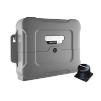
• C/E Series unit
• DVM (Digital Volt Meter)
• 12V dc 10A PSU (Power Supply Unit)
• Type 1 pump
• A conventional 330 Ohm resistor, rated at 1 Watt
Initial inspection checks
Before applying power to the Course Computer carry out following visual inspections:
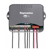
1. Remove the connector cover, the PCB retaining screw and slide the PCB out of the case.
1. Check that the two fuses, F1 (15A), F2 (2A) are the correct rating and not blown.
2. Visually inspect the PCB for any obvious signs of component damage or blackening, paying particular attention to the
FETs and main power components.
3. Check that capacitor C43 polarity is correct (see Tech Update TU228 on page 14)
4. Check that resistance value of R18 matches the requirement of the gyro fitted (see Tech Update 332 on page 16)
Rate gyro connection
The plug is designed to fit one way into the socket. Check the plug is correctly inserted and fully seated.
Detailed diagnosis
Before starting testing ensure that the following are connected to the Course Computer:
• Fluxgate compass
• Rudder reference
•Control Head
• 330 Ohm resistive load to the clutch terminals
• C/E Series display connected via NMEA 1 (do not connect the C/E Series unit via SeaTalk)
Unless otherwise stated, the following tests should be carried out with 12V applied to the Course Computer.
If the unit fails any of the following diagnostic checks (except Step 3), return the PCB to Raymarine and obtain a service
exchange unit. Component level replacement must only be carried out by the factory.
Step 1 - Power checks
Check the voltages at the following locations are correct:
Test point Voltage
+5V-DIG 4.9 V - 5.1 V
HD-PWR 11.95 V - 12.05 V
PWR-0V 0 V
 Loading...