What to do if my Raymarine Receiver shows no AIS data?
J
Julie WallsAug 1, 2025
If your Raymarine Receiver isn't showing AIS data, verify that the AIS input wires are correctly oriented from the multifunctional display's NMEA output. Also, ensure that the display's NMEA output is correctly set to 38.4kbaud.
J
Jessica ChenAug 10, 2025
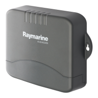
Why is there no vessel data on my Raymarine AIS250?
V
vmckayAug 11, 2025
If you're not seeing vessel data on your Raymarine Receiver, first, place the cursor over the targeted vessel and ensure the ‘AIS DATA’ softkey is not set to ‘OFF’! Next, select the presentation softkey, then the chart layers softkey, and ensure the AIS layer is set to ‘on’. Finally, select the menu button, go to the AIS layer setup menu, and confirm that the displayed target types are set to ‘all’ (if they were previously set to ‘dangerous’).
N
Natasha DaviesAug 20, 2025
What to do if my Raymarine AIS250 Receiver has no power?
S
Sean CampbellAug 20, 2025
If your Raymarine Receiver isn't powering on, check all power connections to ensure they are secure and that the correct voltages and currents are being applied. Also, inspect any relevant fuses to see if they have blown.