Do you have a question about the Raymarine C140 and is the answer not in the manual?
Essential safety warnings for product installation, covering ignition, high voltages, grounding, and power supply protection.
Safety precautions for operating radar scanners and sonar equipment, emphasizing personnel safety during use.
Best practices for routing, types, and lengths of cables for optimal performance and longevity.
Detailed steps and recommendations for connecting the power supply to the C-Series display.
Requirements for grounding Raymarine equipment, including dedicated earthing plates.
Recommendations for breakers, fuses, and circuit protection for the power supply.
Details on connecting displays and devices using the high-speed SeaTalkhs network.
How to connect digital radar scanners to the C-Series display via SeaTalkhs.
Instructions for connecting devices using the NMEA 0183 protocol.
Steps for connecting SeaTalk equipment using the supplied multi-cable.
Details on connecting the C-Series display as part of a SeaTalkng network.
How to connect NMEA 2000 devices using the SeaTalkng bus and appropriate adaptors.
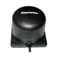
Steps to verify GPS functionality by checking boat position on the chart application.
Steps to check radar operation, including scanner initialization and transmission.
Provides general causes and corrective actions for common problems with marine electronics.
Addresses problems that occur at power up, such as the display not starting.
Solutions for common radar issues like "No Data" messages or scanner problems.
Troubleshooting steps for GPS issues, including "No Fix" status and location problems.
Solutions for sonar problems such as no data source or DSM faults.
Addresses issues where instrument or system data is unavailable at displays.
Explains LED states on the SeaTalkhs switch and their associated causes.
Covers other common problems like erratic display behavior, button issues, and software mismatches.
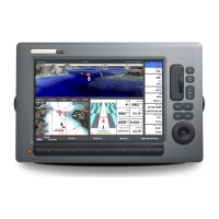
| Chartplotter | Yes |
|---|---|
| Radar Compatibility | Yes |
| GPS Receiver | Yes, integrated |
| Sonar Compatibility | Yes |
| Networking | NMEA 2000 |
| Storage Temperature | +70°C |