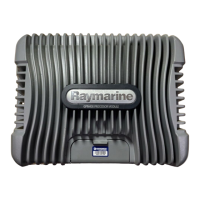
Item
e7/e7D
e95/e97/
c95/c97
e125/e127/
c125/c127
A233mm
(9.17in.)
290mm
(11.42in.)
354mm
(13.94in.)
B144mm
(5.67in.)
173mm
(6.81in.)
222mm
(8.74in.)
C64mm(2.52
in.)
64mm(2.52
in.)
69mm(2.72
in.)
D160mm
(6.29in.)
160mm
(6.29in.)
160mm
(6.29in.)
E180mm
(7.09in.)
212mm
(8.35in.)
256mm
(10.08in.)
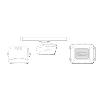
Removingtherearbezel
Youmustremovetherearbezelbeforeush-mounting
thedisplay.
1.Removethefrontbezel.Refertotheseparate
instructionsprovidedforthatprocedure.
D12 184 -2
* = e 7 / e 7D
*2
3
1
= c9 5 / c97 c1 25 / c127 / e 95 / e 97 / e 1 25 / e 127
2.Removethescrewsthatsecurethebezeltothe
display.
3.Carefullyremovethebezelfromtherearofthe
display,pullingthebezelgentlyalongthe:
i.Outeredges-workfromthesidesupwardsand
thenalongthetopedge,ensuringthattheclips
arefullyreleasedfromthedisplay.
ii.Inneredges-ensurethatthebezeliscompletely
removedfromthedisplay.
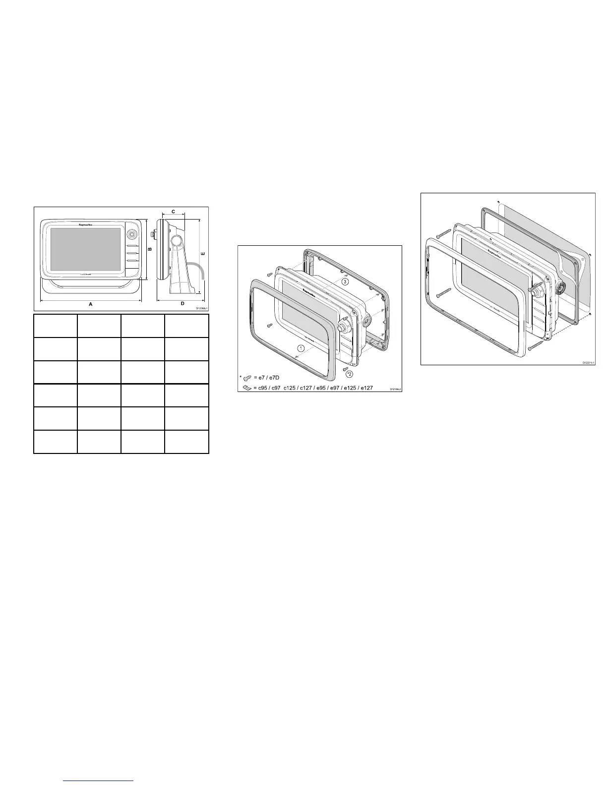
Flushmounting
Youcanmountthedisplayinaushorpanelmounting
arrangement.
Beforemountingtheunit,ensurethatyouhave:
•Selectedasuitablelocation.
•Identiedthecableconnectionsandroutethatthe
cableswilltake.
•Detachedthefrontbezel.
1.Checktheselectedlocationfortheunit.Aclear,
atareawithsuitableclearancebehindthepanel
isrequired.
2.Fixtheappropriatecuttingtemplatesuppliedwith
theproduct,totheselectedlocation,usingmasking
orself-adhesivetape.
3.Usingasuitableholesaw(thesizeisindicatedon
thetemplate),makeaholeineachcornerofthe
cut-outarea.
4.Usingasuitablesaw,cutalongtheinsideedgeof
thecut-outline.
5.Ensurethattheunittsintotheremovedareaand
thenlearoundtheroughedgeuntilsmooth.
6.Drill4holesasindicatedonthetemplatetoaccept
thesecuringscrews.
7.Placethegasketontothedisplayunitandpress
rmlyontotheange.
8.Connectthepower,dataandothercablestotheunit.
9.Slidetheunitintoplaceandsecureusingthe
providedscrews.
15
 Loading...