Do you have a question about the Raymarine Ray 202 and is the answer not in the manual?
Critical warning about device limitations and user responsibility for navigation.
Detailed technical specifications for the RAY 202 radiotelephone.
Technical specifications for the receiver performance and selectivity.
Technical specifications for the transmitter output power and modulation.
Guides on making all necessary electrical connections for the unit.
Detailed instructions for connecting the unit to a 12 VDC power system.
Instructions for connecting the VHF antenna coaxial cable.
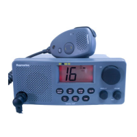
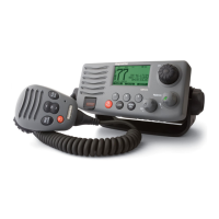
Overview of the RAY 202 front panel controls and LCD display.
Detailed descriptions of each control on the RAY 202 front panel.
Procedures for operating the RAY 202 radiotelephone.
Step-by-step guide for powering on the unit and setting it up.
Explanation of the characters and indicators on the LCD display.
Technical breakdown of the radio's core receiver, transmitter, and synthesizer.
Detailed description of the receiver circuitry components and signal flow.
Detailed description of the transmitter circuitry components and signal flow.
Explanation of the frequency synthesizer's operation and phase-lock loop.
Chart for diagnosing and isolating common circuitry failures.
Procedure for performing a master reset to clear problems and restore factory settings.
| Type | VHF Marine Radio |
|---|---|
| Transmit Power | 25W / 1W |
| GPS Interface | NMEA 0183 |
| Display | LCD |
| Channel Spacing | 25 kHz |
| Modulation | 16K0G3E |
| Weight | 1.2 kg |