Do you have a question about the Raymarine RAY430 and is the answer not in the manual?
Provides an overview of the RAY 430 Multifunction Loudhailer, its capabilities, and warranty information.
Details the key built-in features of the RAY 430, including its multipurpose functions and design.
Lists the technical specifications of the RAY 430, including dimensions, power, output impedance, and frequency response.
Instructions for safely unpacking and inspecting the RAY 430 unit and its components upon receipt.
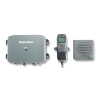
Lists all standard equipment included with the RAY 430 Loudhailer, detailing each item and its part number.
Guidance on proper storage conditions for the RAY 430 components to maintain their integrity before installation.
Considerations for selecting the optimal mounting location for the RAY 430 to ensure dependable and trouble-free operation.
Detailed instructions for making the necessary electrical connections, including DC power, intercom, and hailer horn wiring.
An introduction to operating the RAY 430, emphasizing familiarity with front panel controls for optimal performance.
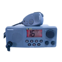
Detailed description of the RAY 430's front panel controls and the functions indicated on its LCD display.
Step-by-step guide for performing various operations, including Hail, Intercom, Fog Horn, and Auxiliary modes.
Presents the block diagram of the RAY 430, explaining the function of each major circuitry component.
General information regarding servicing instructions for the RAY 430 and how to contact Product and Customer Service.
Recommended monthly procedures for preventative maintenance to ensure the RAY 430's optimal performance and longevity.
Details on how to perform adjustments, including test equipment required and specific procedures for Listen and Intercom output.
Comprehensive lists of parts for the Linear A, Linear B, AGC, CPU, and Dim/Hail PCB assemblies.
An exploded view illustrating the assembly of the RAY 430, with numbered components for easy identification.
Detailed list of parts corresponding to the numbers in the assembly drawing, including quantity and part numbers.
Diagram showing the internal wiring connections between the various PCBs and components of the RAY 430 unit.
Schematic diagram illustrating the electrical circuits of the RAY 430, broken down by functional sections.
Diagram showing the component layout on the top and bottom views of the Linear A PCB.
Diagram showing the component layout on the top and bottom views of the Linear B PCB.
Schematic diagram detailing the electrical circuits of the CPU section of the RAY 430.
Diagram showing the component layout on the top and bottom views of the CPU PCB.
| Type | VHF Marine Radio |
|---|---|
| Output Power | 25W / 1W |
| GPS Interface | NMEA0183 |
| Display | LCD |
| Channels | International |