Do you have a question about the Raymarine Ray 53 and is the answer not in the manual?
Overview of the RAY53's VHF capabilities and channel usage.
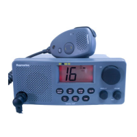
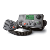
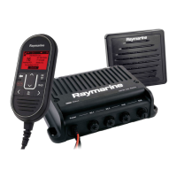
Description of the radio's physical controls and screen elements.
How to use the channel selection knob to change channels.
Adjusting the squelch level using the squelch knob.
Operating the volume knob for audio control and power on/off.
Functionality of the SCAN/MEM key for scanning and memory operations.
Using the WX/INT key for weather channels and frequency modes.
Operation of the MON/1/25 key for monitor mode and power output.
Function of the 16/9 key for channel switching and priority channels.
Using the Push-To-Talk key for transmission.
Using the UP key to increase channel numbers.
Using the DOWN key to decrease channel numbers.
Using the DISTRESS key to send a DSC Distress Call.
Details of the indicators and information shown on the LCD screen.
Indicates when the DSC mode is active.
Indicates when Weather Channel (WX) is active.
Shows when International channels are programmed.
Shows when Canadian channels are programmed.
Indicates when a channel is memory-registered.
Indicates when the radio is in scan mode.
Indicates acknowledgment in DSC mode.
Indicates when the radio is in monitor mode.
Shows when the transmitter is active.
Indicates when the transmitter is operating at 1 Watt.
Shows audio volume level with a bar graph.
Shows squelch level and AUTO squelch status.
Indicates valid NMEA data reception.
Displays the current channel number.
Displays the Priority Channel number.
Procedure for turning the radio on.
How to adjust the audio volume level.
Switching between 1 Watt and 25 Watt transmitter power.
Methods for selecting radio channels.
Selecting between US, International, and Canadian frequency modes.
Steps for transmitting audio using the microphone.
Procedure for selecting and using Weather Channels.
How to activate and use the Priority Channel feature.
Storing and clearing channels in memory.
Overview of All-Scan and Memory Scan modes.
How the All-Scan mode operates.
How the Memory Scan mode operates.
Using Dual Watch and Tri Watch monitoring features.
Details of how Dual Watch monitoring functions.
Details of how Tri Watch monitoring functions.
How carrier detection affects monitoring on Working CH.
How carrier detection affects monitoring on Priority CH.
How weather alerts affect monitoring.
Key operations while monitoring is active.
Procedure for detecting and responding to weather alerts.
Introduction to Digital Selective Calling (DSC) functionality.
Procedure for entering the vessel's MMSI number.
Making and receiving individual ship calls using DSC.
Methods for clearing Other Ship's MMSI numbers.
Checking previously entered other ship MMSI numbers.
How the unit responds to incoming Individual Ship Calls.
Making a general call to all ships using DSC.
Initiating and handling Distress Calls via DSC.
Receiving and responding to Distress Calls.
Configuring the DSC Watch mode (ON/OFF).
Technical specifications for the transmitter.
Technical specifications for the receiver.
Overall structure and major sections of the RAY53.
Details of the CPU and its control functions.
Description of transmitter, receiver, and PLL circuits.
Explanation of the Phase Lock Loop circuit.
How the transmitting circuits operate.
Operation of the microphone amplifier circuit.
Function of the transmit power amplifier circuit.
Description of the APC (Automatic Power Control) circuit.
How DSC signals are processed.
Description of the receiver circuitry.
Function of the antenna switching circuit.
Operation of the high frequency amplifier.
Details of the first intermediate frequency amplifier.
Function of the second intermediate frequency circuit.
Description of the low frequency audio circuits.
How audio muting is controlled.
Detection of Weather Alert signals.
Processing of DSC signals in the receiver.
Adjusting the PLL for the receiver.
Adjusting the PLL for the transmitter.
Adjusting the transmitter frequency.
Adjusting the transmitter modulation.
Adjusting transmitter output power.
Adjusting receiver RF sensitivity.
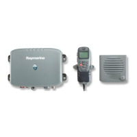
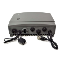
Connecting DC power, external speaker, and NMEA input.
How to connect the VHF antenna.
Recommendations for optimal antenna placement.
Proper grounding procedures for the unit.
| Type | VHF Marine Radio |
|---|---|
| Frequency Range | 156.000 - 163.425 MHz |
| GPS Integration | Yes |
| DSC Capability | Yes |
| Waterproof Rating | IPX7 |
| Speaker Output | 1W |
| Supply Voltage | 12V DC |
| GPS Interface | NMEA 0183 |
| Channels | International |
| Power Output | 25W |
| Display | LCD |