lmportant: Ensure that
the tabs on the split-ring
(labelled
'B'
in the illustration),
are closest to the
cable-end
of the connectoI
rhe too/
widens the
sap
in the sptit,:i?
":ubji:s
t
:jffiJ:if:jiLrd']11:'#n:T"".:!ltdi::t"1?"
the split ring
to be
pushed
further back
onto the
Gttn"
trg, on
the locking collar
(labelled,D,in
the
connector in
the
following
step'
illustration)
pass
through
the channels
(labelled
'E')
lmportant:
Always use the supplied tool
when
attaching
the split ring. The split ring may
become
overstretched and
break if
you
try to attach it without
using the tool.
in the split-ring.
4. Use
the tool to
gently
lever the split ring
over the
moulding
on the connector until it snaps into
position
approximately
0.5 cm further
back
towards the
cable-end of the connector
$w"5s$
The split-ring slides easily for approximately / cm
onto
the connectoc before butting up against the
connector moulding.
Carefully insert the
pointed
end of the supplied tool
into the spiit ring's
gap
(labelled'C'in
the
illustration).
You
can now remove the tool. The split-ring stays in
position
on the connectot; but
rotates
freely.
Slide the O-ring over
the end
of the
connector,
and ensure that it is seated squarely
against the
connector moulding, adjacent to the split-ring.
The locking collar slides easily towards the
plug-end
of the connectot before butting up against the
splitring moulding.
Grasp the body of the connector with one hand, then
with the other
hand,
pull
the locking collar
firmly
towards the
plug-end
of the connector.
ffi l\\g*sr@
":r
&f
)"t
RealVision"
3D transducer extension
cable
For best
performance,
cable runs
should
be kept to a
minimum. However, for
some
installations
(including
all
split-pair
transducer installations) it may be necessary
to
extend the transducer cable.
.
3 m
(9.8
ft), 5 m
(16.4
ft), and 8 m
(26.2
ft) transducer
extension cables are available
(part
numbers:
3 m -
480475, 5 m
-
480476, 8 m
-
A8O477).
.
lt is recommended that
a
maximum of two
cable
extensions are used, with the total cable length not
exceeding 24 m.
Cable
ferrite installation
Your
product
is supplied
with
a cable
ferrite. To ensure
EMC Compliance, the supplied ferrite must be
fitted to
the
power
cable according to the following
instructions.
As
you pull
the /ocking collar it clicks
into
place
over
the split-ring. The locking
collar
stays in
position
on
the connectot but rotates free/y.
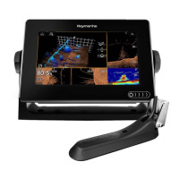
Making
connections
Follow the steps below to connect the transducer cable
to
your
multifunction display.
1. Ensure
that the
vessel's
power
supply
is
swltched off.
2. Ensure that the multifunction
display
has been
installed in accordance with the installation
instructions
supplied with it.
3. lf
your
installation
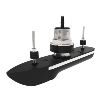
comprises split-pair
transducers:
i. Connect the cable from each transducer to the
Y-cable tails
(A8O478);
check the colored labels
on the cables
to ensure that the
transducers are
connected to the
correct
Y-cable tail.
ii.
Connect
an
extension cable
to
the
remaining
free
plug
on the Y-cable. See Realvision'" 3D
transducer extension cable.
4. Ensuring correct orientation,
push
the transducer
cable
(or
extension cable) connector fully onto
the corresponding
connector on
the multifunction
display.
5. Turn
the locking collar clockwise to secure the cable.
t.
2.
3.
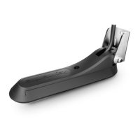
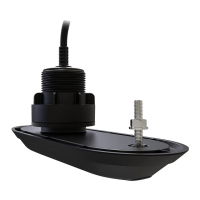
Transducer connector.
The
supplied cable ties
should
be used to secure
the ferrite in
position.
Fit the supplied ferrite to the transducer cable,
ensuring a tight
fit. The ferrite
should
be fitted as
close
as
possible
to the connector, but ensure that
the distance between the ferrite and the top
of the
connector
is no more
than 150
mm
(5.9
in).
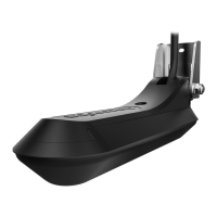
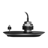
Transducer cable.
a
a
:
I
 Loading...