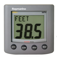
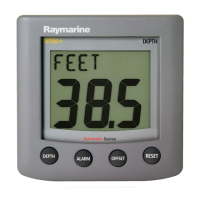
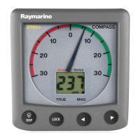
ST60 Graphic Display
Installation Guide
www.raymarine.com
®
Raymarine Ltd, Portsmouth, Hampshire, UK PO3 5TD
Raymarine Inc. Nashua, NH 03063-4219, USA
Recyclable Material - Please dispose of responsibly.
+44 (0) 23 9269 3611
Toll Free: 800-539-5539
+1 603-881-5200
N
M
E
A
I
N
N
M
E
A
O
U
T
Connection details
D6466-1
Blue RedBlue Red
SeaTalk cable
SeaTalk cable
Use the procedures in the ST60 Graphic
Display Commissioning Guide to set the
function for the NMEA OUT connector.
Either:
Data out to NMEA system
or
External alarm signals to Auxiliary Alarm
6 mm
50 mm
3 mm
Data in from NMEA
system
Site requirements
Running cables
Check
Min 9 in (230 mm)
Min 20 in (500 mm)
D6464-2
D6465-1
Instrument edge
Sun cover edge
Drill hole,
6 mm (1/4 in)
diameter in
4 positions
109 mm (4.3 in)
114 mm (4.5 in)
UP
Remove material
from shaded area only
ST60 Graphic Display
FLUSH MOUNT
Template
Flush mount template
Parts supplied
Tools required
Connector (x2)
Stud (x2)
Thumb nut (x2)
SeaTalk Cable
Sun cover
Gasket
ST60 Graphic Display
(ready for
surface mounting)
Auxiliary Alarm option
Flush mount option
Auxiliary Alarm
Grommet
Connector
block
Bezel
Gasket
Bracket
Power Drill
3
/16 in (5 mm) Drill
1
/4 in (6 mm) Drill
3½ in (90 mm) Hole Cutter
Pencil
Jig saw
(only required if
flush mounting
the Display)
D6463-1
Adhesive tape
87022-1