P/N 241417Rev 4
Effective: 12-04-12
Replaces: 10-07-11
Page 9
REPLACEMENT CONTROL BOARD - ALL MODELS
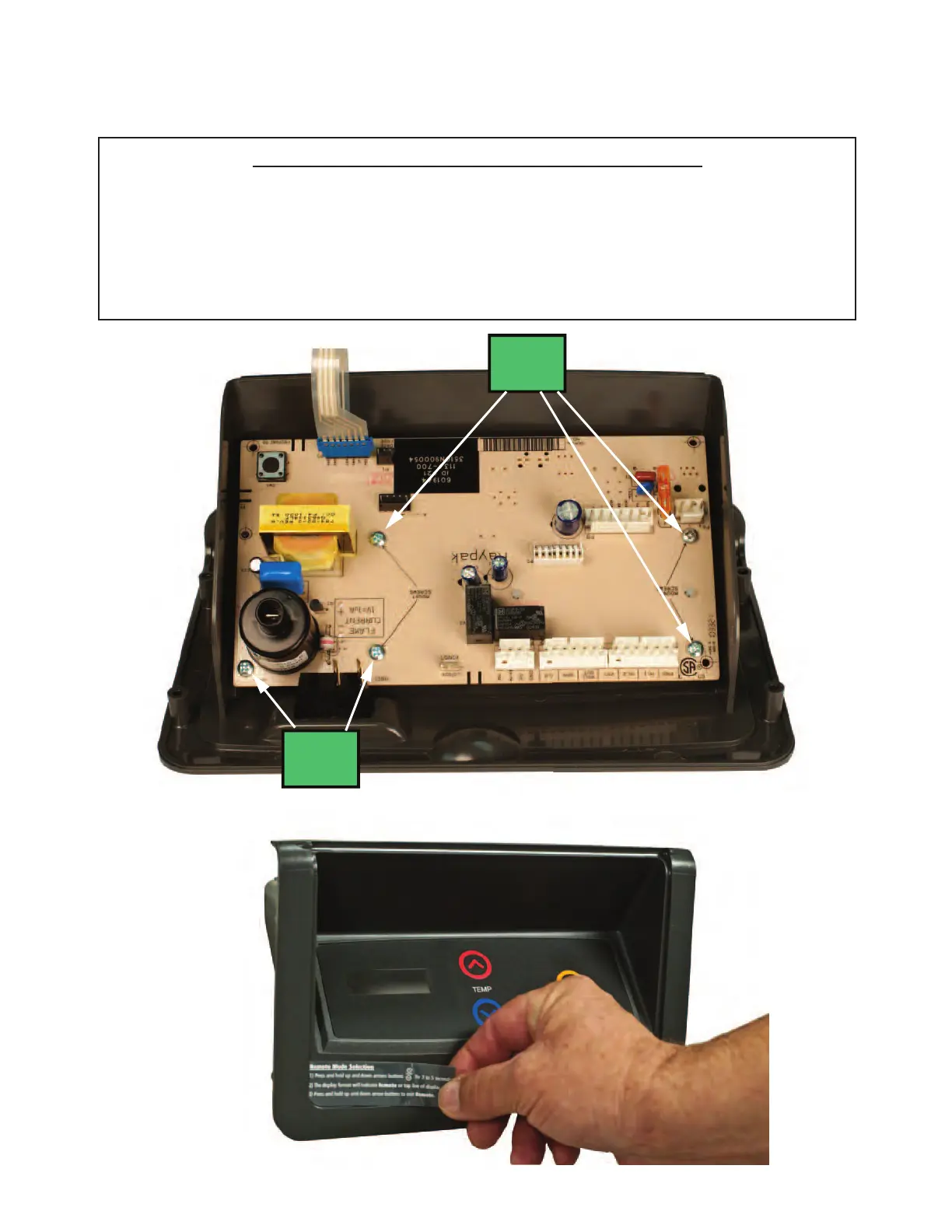
1. Mount the replacement control board to plastic bezel using (5) five mounting screws as
shown in Fig. 20.
2. Reconnect all cable connections.
WARNING: See page 10 for specific directions on
connecting P2 and P4.
3. When installation is complete, attach the new Remote Mode Label as shown in Fig. 21.
Fig. 20
Fig. 21