11
Electrical Connections
Refer to the unit rating plate below the control panel
for precise power requirements for your unit, and for
ampacity and over-current protection requirements.
All wiring must be in accordance with the National
Electrical Code, NFPA No. 70, latest edition, and all
applicable state and local codes. Wiring diagram is
located on page 46.
• Locate the equipment disconnect means within 3
feet (0.9m) of the heater’s electrical enclosure, or
as close to the heater as possible. Always satisfy
applicable codes and standards.
• In sizing power wiring, be especially aware of
up-sizing requirements necessary due to wiring
distances. Always satisfy applicable codes and
standards.
• Electrical installation should be done by a licensed
electrician only.
This unit is pre-wired to work with external control
systems, heat-on-demand options and other external
time clock overrides. Refer to the external control
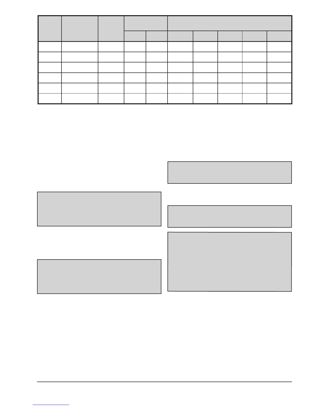
* Reference only - see National Electric Code or local codes for wire gauge length limits.
Table A: Typical System Electrical Power Requirements
NOTE: Refer to the National Electrical Code,
Article 680, for general requirements for swimming
pools and equipment, and to Article 440 for special
considerations necessary for circuits supplying
hermetic refrigeration motor/compressors.
WARNING: This unit MUST be installed using
flexible conduit for supply wiring to the unit. This
will allow movement of the conduit whenever the
junction box is removed for service - see instructions
on page 40.
system’s instructions, and page 31 of this manual, for
installation information.
An earth ground lug is located to the right side of the
water connections.
Water Connections
1. Connect the heat pump pool heater in the return
water line between the filter and the pool/spa. See
the Plumbing Diagrams beginning on page 42.
2. Connect the filter outlet to the fitting marked
INLET/ENTREE at the bottom front of the unit.
3. Connect the fitting marked OUTLET/SORTIE to
the return piping to the pool/spa. Unit inlet/outlet
connection fittings are 1-1/2-inch PVC unions on
models 2450-4450 and 2-inch PVC unions on
models 5450-8450.
CAUTION: The heat pump pool heater inlet and
outlet connections are NOT interchangeable. They
must be connected as instructed below.
NOTE: The earth ground lug may be relocated
to the left side of the water connections as needed
during unit installation.
WARNING: Improper installation of any type of
automatic chemical feeders can result in serious
damage to, or premature failure of, the heat
pump pool heater and may void the heat pump
pool heater warranty. Install a check valve and/or
a Hartford loop AFTER the heat pump pool heater
and BEFORE any chlorinating devices. Install any
automatic chemical feeders AFTER the heat pump
pool heater.
Model
No.
Power
Min.
Circuit
Ampacity
Breaker Size (A)
Recommended Wire Length from Breaker to
Heater*
MIN. MAX. 12 AWG 10 AWG 8 AWG 6 AWG 4 AWG
2450 208/230-1-60 22 30 35 77 ft 123 ft 197 ft 312 ft 500 ft
3450 208/230-1-60 29 35 50 NR 94 ft 151 ft 239 ft 383 ft
4450 208/230-1-60 32 40 50 NR 89 ft 142 ft 225 ft 359 ft
5450 208/230-1-60 30 40 60 NR 94 ft 151 ft 239 ft 383 ft
6450 208/230-1-60 34 50 60 NR 97 ft 156 ft 247 ft 396 ft
8450
208/230-1-60 42 50 60 NR NR 110 ft 175 ft 280 ft
 Loading...