41
3. Remove the multi-pin connectors from the back of
the control board (8 connectors in total) – NOTE:
You do not need to remove the PL4 connector as
this is the ribbon cable from the membrane switch
mounted on the control panel.
4. Set the control panel cover aside to reinstall when
service is completed.
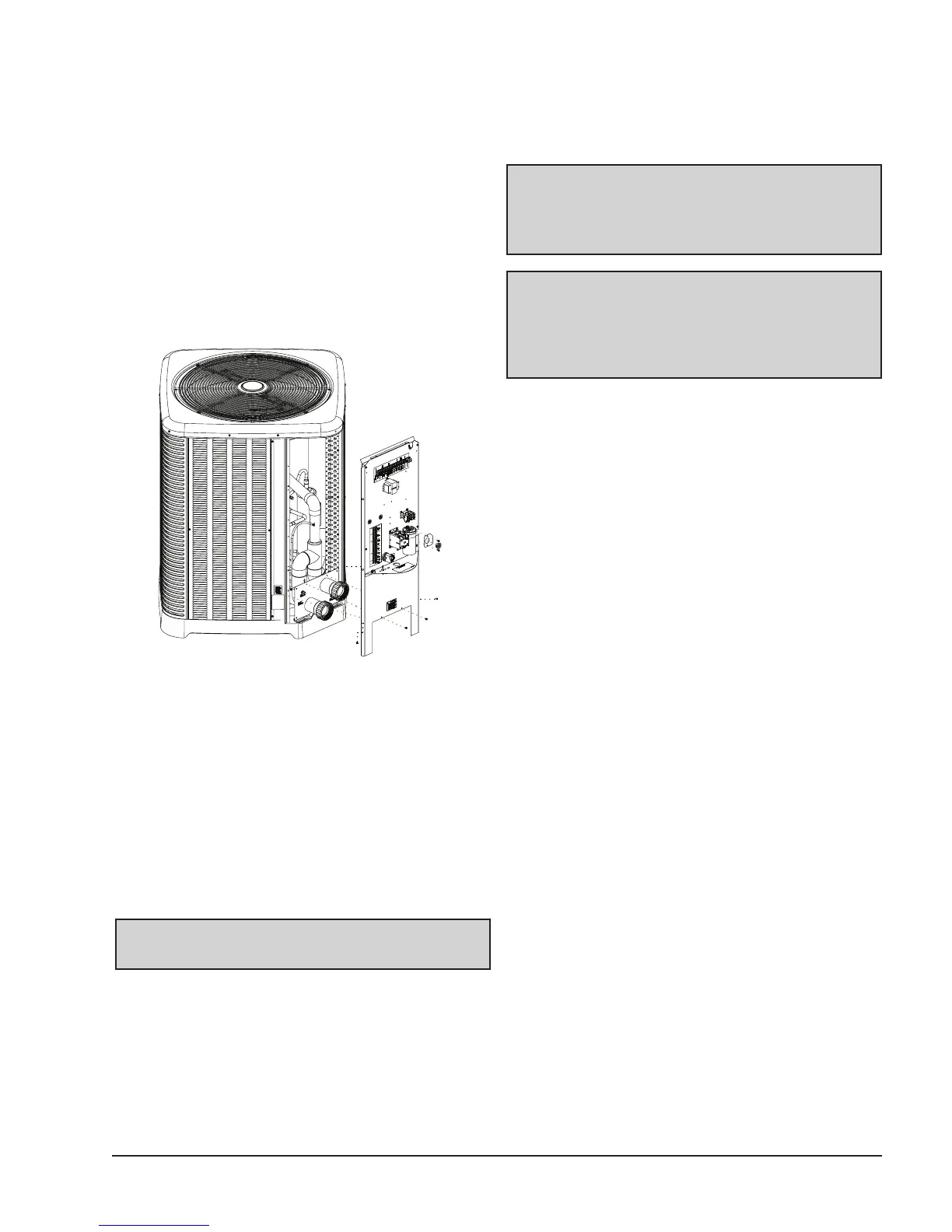
5. Remove the 4 screws securing the junction box
panel to the cabinet (1 each side and 2 by Inlet/
Outlet water connections). See Fig. 11. Place the
screws in the recessed cups in the molded base.
6. Remove the 2 screws holding the compressor wire
retainer to the junction box and place them in the
recessed cups in the molded base.
7. Slide the compressor wires out the side of the slot
in the junction box.
8. Lift the junction box slightly (hold onto the bottom
of the junction box like a handle) and pull out at
the bottom to remove the junction box assembly.
WARNING: Care must be taken with the fan and
compressor wires when removing junction box.
9. Slide assembly away from the opening to give
access inside the unit. NOTE: The top of the
unit may also be removed for greater access as
desired.
Fig. 11 : Sheet Metal Screws to remove Junction Box
Panel
10. After service, reposition the junction box and insert
the top first and lift up until the bottom slides into
place against the cabinet and the panel where the
Inlet/Outlet water connections are secured.
11. Reinstall the compressor wire retainer to the
junction box with the 2 screws removed in Step #6.
12. Reinstall the screws removed in Step #5 to secure
the junction box to the cabinet.
13. Reconnect the multi-pin connectors to the control
board.
14. Slide the control box cover into place and secure
with the screws removed in Step #2.
15. Turn ON power and start operation as needed.
CAUTION: Ensure that the fan motor wires are
routed into the slot at the top of the junction box.
Also ensure that the compressor wires are routed
into the slot on the right side of the junction box.
WARNING: If any wires have come off components
during service of this unit, please refer to the wiring
diagram on the back of the control panel cover or in
the I&O manual to ensure that they are returned to
the correct terminals/locations.
 Loading...