SECTION C: Installation
20
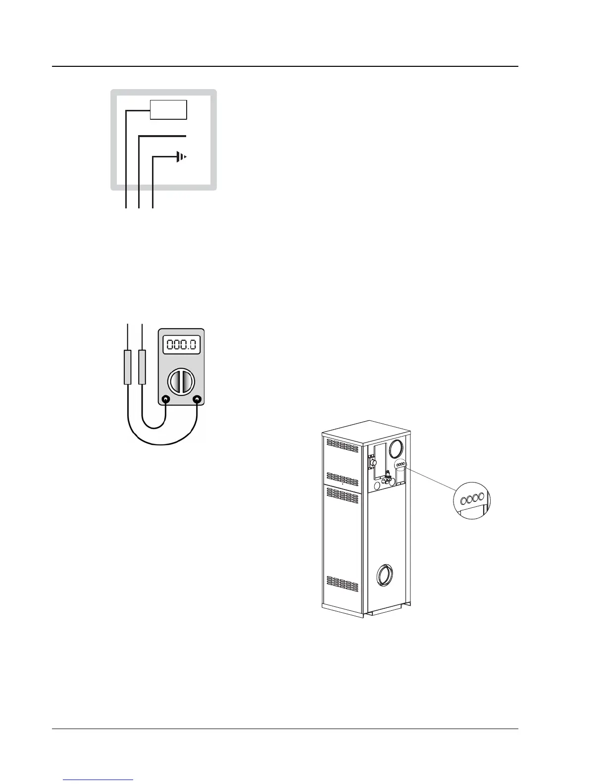
CIRCUIT
BREAKER
WHITE
GROUND
BLACK
GREEN
ABC
Fig. 17: Wiring Connections
Check the power source:
AC = 108 VAC Minimum, 132 VAC MAX
AB = 108 VAC Minimum, 132 VAC MAX
BC = <1 VAC Maximum
Fig. 18: Multi-meter
Making the Electrical Connections
Refer to Fig. 16-19.
1. Verify that circuit breaker is properly sized by
referring to heater rating plate. A dedicated circuit
breaker should be provided.
2. NOTE: Current draw noted on rating plate does
not include pump current.
3. Turn off all power to the heater. Verify that power
has been turned off by testing with a multi-meter
prior to working with any electrical connections or
components.
4. Observe proper wire colors while making electri-
cal connections. Many electronic controls are
polarity sensitive. Components damaged by im-
proper electrical installation are not covered by
warranty.
5. Provide overload protection and a disconnect
means for equipment serviceability as required by
local and state code.
6. Install heater controls, thermostats, or building
management systems in accordance with the appli-
cable manufacturers’ instructions.
7. Conduit should not be used as the earth ground.
NOTICE: A grounding electrode conductor shall be
used to connect the equipment grounding conductors,
the equipment enclosures, and the grounded service
conductor to the grounding electrode.
Field Wiring Connection
CAUTION: Label all wires prior to disconnection
when servicing controls. Wiring errors can cause im-
proper and dangerous operation. Verify proper
operation after servicing.
DANGER: SHOCK HAZARD
Make sure electrical power to the heater is discon-
nected to avoid potential serious injury or damage to
components.
Fig. 19: Wiring Location