SETUP & OPERATON HeatNet Control V3
Page 20
available” state, it can still be fired locally and failsafe is
still available.
SETUP: AUX FUNCTIONS: HEAT EXCHANGER:
SEND RETURN:
OFF The Master sends its return
temperature to all boilers
RETURN The Master sends its return
temperature to all boilers
SYS RET The Master sends the system
return temperature to all boilers
SETUP: AUX FUNCTIONS: HEAT EXCHANGER:
LOW TEMP:
OFF No check is made to the return
temperature – boiler remains
online
RETURN Uses the boilers own return
sensor (No pump /valve present)
SYS RETURN Uses the System Return temp
received from the Master Boiler
(its Local or System Return).
SETUP: AUX FUNCTIONS: HEAT EXCHANGER:
TEMP < 140F
Adjustable threshold temperature below which the
boiler will take itself offline.
1 degree F of hysteresis is provided so as to not
toggle offline<-to->online at the threshold temp.
Since the FIII boiler is non-condensing, the efficiency vs.
input is relatively flat. The MOD MAX value will not have
the same impact if the FIII non-condensing boilers were
placed in the Priority 1 set.
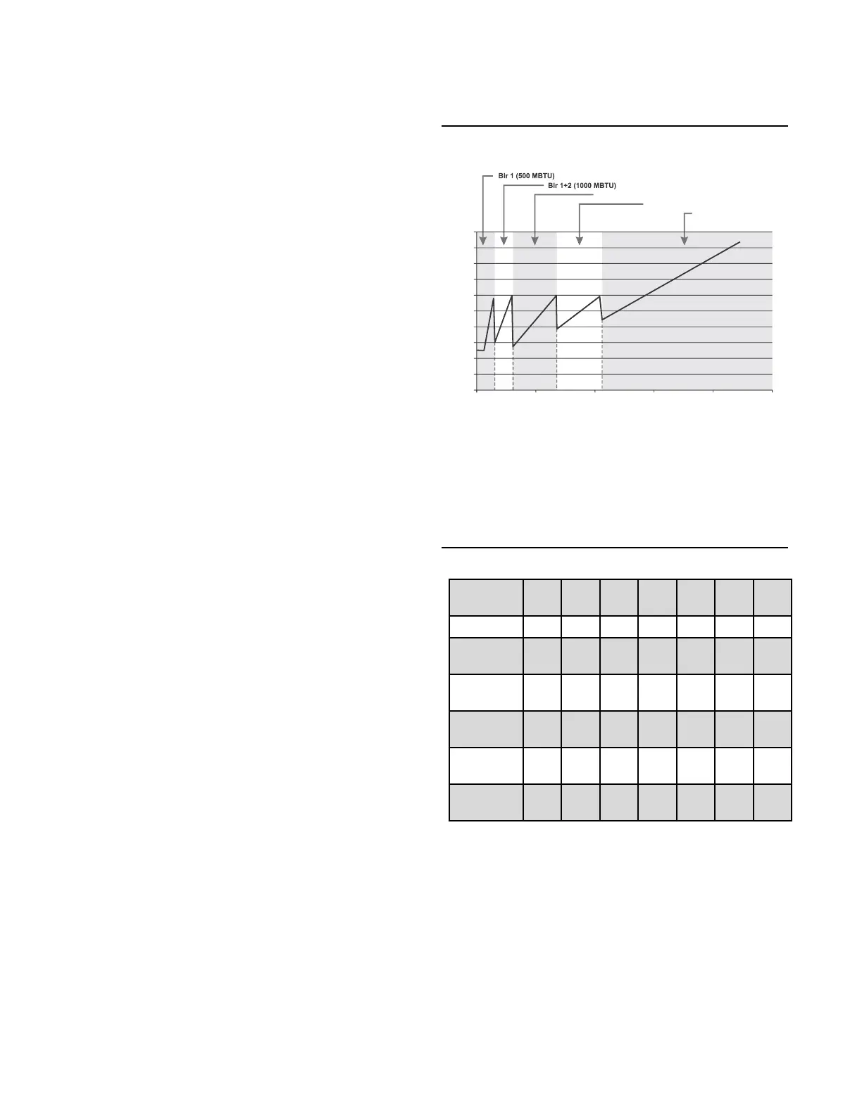
Futera III/ Fusion Boiler BTU Chart
In the Mixed Boiler System table (Figure 15) line 2
example, (2) CB/CW 500s are set as Priority 1 and (3)
MB/MW 1250s set as Priority 2. With a MOD MAX of
60%, each 500 can run to 300M (600M total) before a 1250
is called ON (Add Delay timer). Once both 500s are running
and the 1250 is called on and running, all (3) boilers will
drop to a total of the 600M BTUs: The sum of the 500, 500,
and 1250 would equal about 27% modulation: (.27 * 500M)
+ (.27 * 500M) + (.27 * 1.25MM) or: 135M +135M + 337M
= 607M and operate at higher combustion efficiencies: 27%
is roughly between the top two lines on the Typical
Efficiency of Condensing Boilers chart.
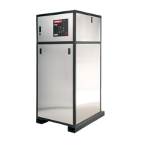
The Boiler System Response 5 chart illustrates how each
boiler (in the example) is brought on and fires to 60%, drops
to a lower fire rate and then adds the next boiler (vertical
dashed lines). Once all boilers are firing, the modulation is
released allowing all boilers to fire to 100%.
Figure 15 Boiler System Response 5
(2) CB/CW 500s, (3) MB/MW 1250s
So, for the first 600 MBTH of load, the combustion
efficiency is maximized by running the (2) fusion boilers
from low to middle input rates. Running the (2) fusion
boilers first also has the added effect of minimizing the
return water temperatures of <140F from reaching the
noncondensing boilers.
Figure 16 Futera III/Fusion Boiler Btu Chart (MBH)
 Loading...
