CONTROL METHODS HeatNet Control V3
Page 25
The System Setpoint Timer also needs to be loaded
periodically to allow the H-Net system to fallback to
Method 1 in the event communications is lost from the
Building Management System (BMS).
This feature can be turned off in ADVANCED SETUP:
COMMUNICATIONS: SETPOINT TIMER: OFF. If the
setpoint timer feature is set to ON, the ADVANCED
SETUP: COMMUNICATIONS: SETPOINT TIME may be
set to a time that allows any write to a MODBUS register to
reset the setpoint timer as long as it occurs within that time.
This will reset the setpoint timer without writing the
setpoint timer register. So, periodically writing the setpoint
register will automatically reset the setpoint timer as long as
the write occurs within that time window. The MODBUS
protocol allows writing and reading registers using
MODBUS commands.
Protocessor option
An optional BACnet or LonWorks bridge module can be
used to connect the MODBUS network to a BACnet or
LonWorks network. Use communications default settings.
Figure 22 Protocessor bridge module option
This method allows enabling and disabling the boiler or H-
Net system, changing setpoints, reading boiler(s) status, or
temperatures remotely using digital commands. See the
section: MODBUS Communications.
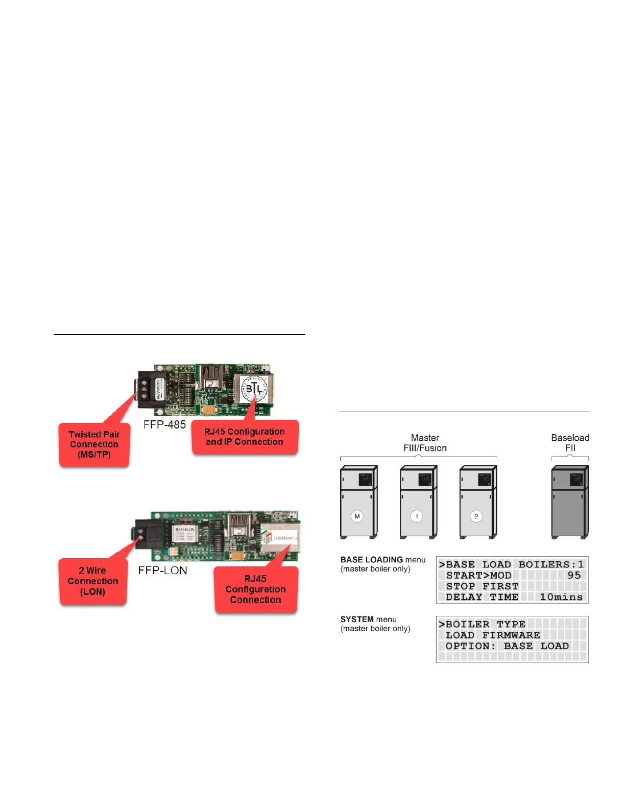
Base Loading, Relay Control
The H-Net control has the ability to control (1) base load
boiler using the K8 Relay contacts on J4 pins 2 & 6. In
order to connect to this plug, (2) wires with pins are
required and inserted in J4. Base Loading via relay requires
these (2) flying leads (loose wires available from the
factory) to be inserted into J4, pins 2 & 6. These (2) wires
then make up the Normally Open contacts. This feature can
be used on Master or Member boilers. The solid state relay
K8, with contact connections on J4.2 & J4.6 has a rating of:
0.1 to 1 Amp.
If the base load boiler is of the modulating type, a 4-20mA
signal is also provided on J4 pins 1 and 5. Jumper shunt JS1
will then need to be set to 4-20mA position. Two additional
wires (available from the factory) will need to be added to
the J4 pins at 1 & 5. Pin 1 is the + output of the 4-20mA
transmitter, and pin 5 is the – output. This modulating
control signal is used to modulate the base load boiler along
with the HeatNet boilers in parallel. The ADAPTIVE MOD
does not function in lowering the modulation rate when the
base load boiler is added. The PID will adapt to the newly
fired base load boiler and lower its modulation rate when
the increase in water temperature is observed.
Figure 23 Base loading with Futera II boiler
 Loading...