101
14 - USE
14.14 - “Installer’s
menu”
CAUTION!!!
Changing these
parameters could cause
the heater and therefore the
system to malfunction. For
this reason, only a qualifi ed
technician who has in-depth
knowledge of the heater should
change them.
The heater’s micro-processor makes
this menu of parameters available to
the qualifi ed technician for diagnostic
and adjustment of the appliance to the
system.
When entering the “Installers’ Menu”,
the display in Figure 14-1, will start to
show the icon and parameters
over 2000 indicating that a change of
mode has taken place.
To access the “Installers’ Menu” (see
also Section 18 to better understand
the several menus) proceed as follow:
1. press and hold together buttons
RESET and
for 5 seconds
until the
icon is displayed;
2. release the two precedent buttons;
3. press and release the and
buttons to scroll through
the list of the parameters;
4. once the parameter has been
displayed, it can be changed
pressing the RESET button (value
start to blinking) and using the
and keys you can
change the value;
5. press and release the RESET
button to confi rm the amended
data before moving to the next
parameter.
6. To exit the “installers’ Menu”, press
and hold RESET button for more
than 5 seconds until the
icon
stops to be displayed.
NOTICE! If no key is pressed for
more than 60 seconds, the control
automatically exits the “Installers’
menu”. Any parameter change not
saved using the RESET button, will
be lost.
For heaters models 399 up to 1000
parameters adressed to “Burner 1”
are applicable for that burner only. If
you want to see the same parameters
for the other burners you have to
connect the display to the burner
you want to see. To do this follow
procedure in Section 15.7.
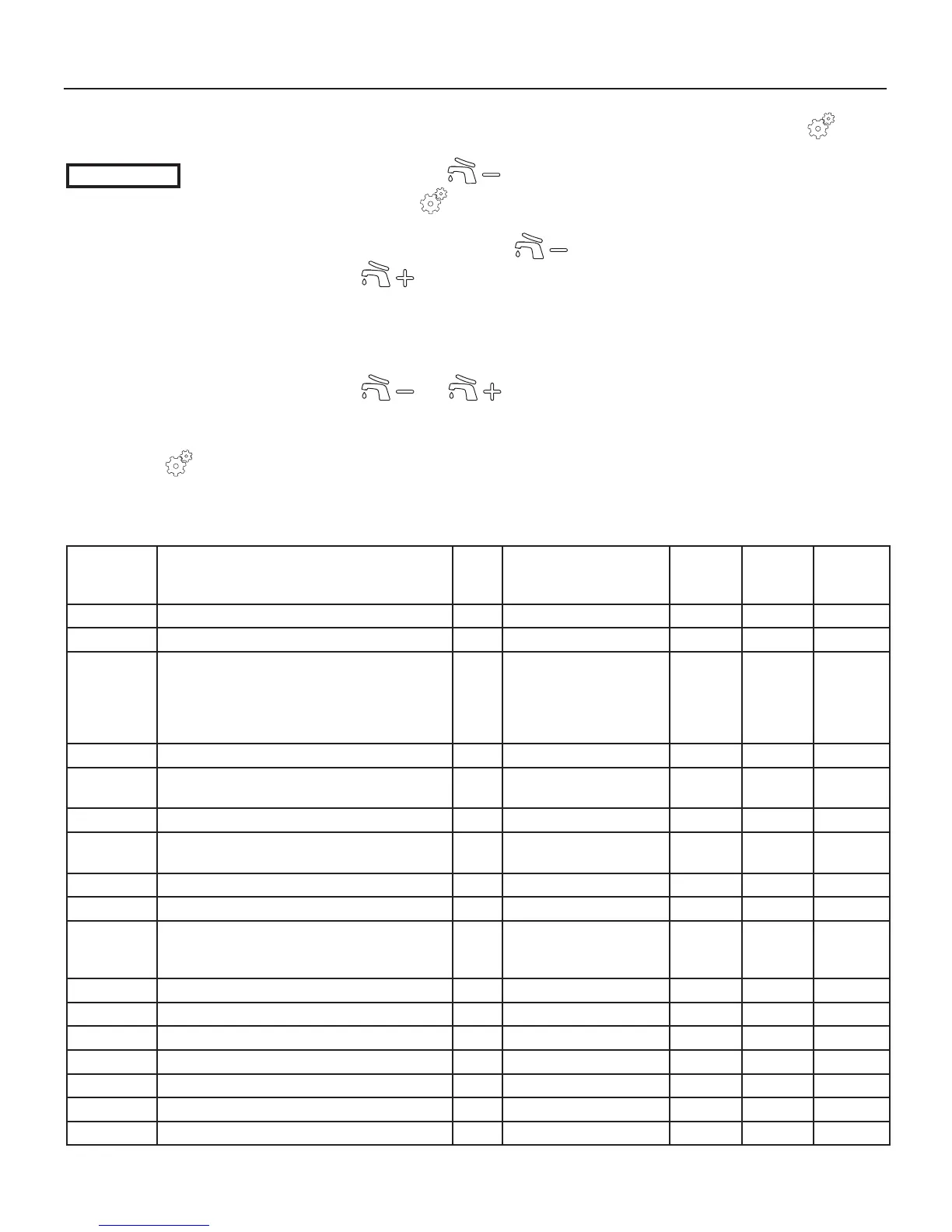
The next table lists each parameter,
what it affects and its adjustment
range.
Custom value column is at your
convenience to record changed
values in the event you need to
change the control board.
Continue
Parameter Parameter’s description M.U. Range Boilers’
factory
settings
W.Heat.
factory
settings
Custom.
value
2001 Burner 1 minimum Power % 1 to 50 1 1
2002 Burner 1 maximum Power % 1 to 100 100 100
2003 CH mode nn 00: CH with thermostat;
01: CH with outdoor reset;
02: CH N/A;
03: CH N/A;
04: CH with 0-10 Vcc input
00
2004 Burner 1 Wait time after max differential sec 10 to 30 30 30
2005 Local post pump time (and of the Burner 1
Motorized valve)
sec 10 to 900 240 240
2010 System test: Burner 1 (Master) \ Off, Low, Ign, High OFF OFF
2011 System test: Local pump (and of the Burner 1
Motorized valve)
\ On or OFF OFF OFF
2012 System test: CH pump \ On or OFF OFF OFF
2013 System test: DHW pump \ On or OFF OFF OFF
2014 Display test (when RESET button is pushed all
display icons will light-on. Next RESET buttons
back in settings menu)
\\ \ \
2020 Warm weather shutdown temperature °F 32 to 95 69 N/A
2021 Reset curve design: winter outdoor temperature °F -4 to 41 24 N/A
2022 Reset curve design: winter supply temperature °F 32 to 176 176 N/A
2023 Reset curve design: spring outdoor temperature °F 32 to 86 69 N/A
2024 Reset curve design: spring supply temperature °F 32 to 104 104 N/A
2027 Night setback temperature °F 2 to 90 18 N/A
2042 Burner 1 anti cycling: time sec 10 to 900 180 180
 Loading...


