67
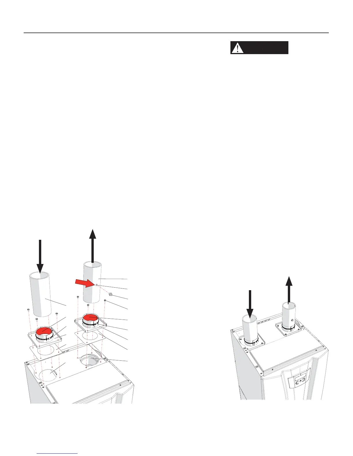
Figure 11-9 PVC/CPVC air intake/
vent connection
11 - INSTALLATION - Vent and combustion air
11.7.2 - PVC/CPVC air
intake connection
Combustion Air Intake
connection (see Figure 11-9
Item “M”). This connection is used
to provide combustion air directly to
the heater from outdoors. Combustion
air piping must be supported per
guidelines listed in the National
Mechanical Code, Section 305, Table
305.4 or as local codes dictate.
To connect a PVC/CPVC pipe to the
air intake connection proceed as follow
while referring to Figure 11-9:
1. install heater adapter “P” above inlet
air opening “M” with gasket “D” and
bolts “E”;
2. Prepare the connection between
adapter “P” and pipe “N” like
described on Section 11.7.1;
3. Insert the air inlet PVC/CPVC pipe,
for 3” into the adapter “P”;
4. tight the clamp “F” to mechanically
secure the adapter “B” to the pipe.
A = Glue (Field provided)
B = Flue exhaust adapter for
PVC/CPVC pipe (Factory
supplied)
C = Flue exhaust connection
D = Gasket
E = Fixing screw
F = mechanically secure clamp
G = PVC/CPVC exhaust pipe
(Field provided)
H = Combustion analization
probe (Field installed)
L = cap (Field provided)
M = Air intake connection
N = PVC/CPVC air inlet pipe
(Field provided)
P = Air intake adapter for PVC/
CPVC pipe (Factory supplied)
11.7.3 - PVC/CPVC vent
connection
Vent connection (see Figure
11-9 Item “C”). This connection
is used to provide a passageway for
conveying combustion gas to the
outside. Vent piping must be supported
per the National Building Code, Section
305, Table 305.4 or as local codes
dictate.
To connect a PVC/CPVC pipe to the
vent connection proceed as follow
while referring to Figure 11-9:
1. install heater adapter “B” above fl ue
exhaust opening “C” with gasket “D”
and bolts “E”;
2. Prepare the connection between
adapter “B” and pipe “G” like
described on Section 11.7.1;
3. Insert the fl ue exhaust PVC/CPVC
pipe, for 3” into the adapter “B”;
4. tight the clamp “F” to mechanically
secure the adapter “P” to the pipe.
C
M
D
A
B
F
D
A
E
P
F
H
G
L
N
020010.01.010
Combustion
air intake
Flue
exhaust
WARNING!!!
Do not
insulate PVC/CPVC exhaust
pipe nor install into an
enclosure, closet, alcove or
any other obstruction thereby
preventing the cooling of the
exhaust pipe. Failure to follow
this warning could result in
excessive levels of carbon
monoxide or a fi re, which can
result in severe personal injury
or death!
Figure 11-10 PVC/CPVC
air intake/Vent connection
correctly in place
Extend the
fl ue exhaust
pipe to
outside
building
020010.01.016
Extend the
air intake
pipe to
outside
building
 Loading...


