23
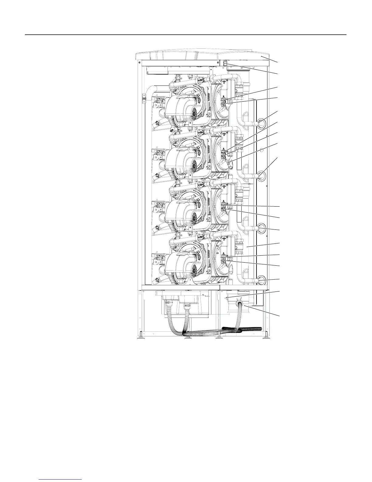
3 - MAIN COMPONENTS
31
31
31
31
22
28
28
28
29
29
28
29
29
30
32
34
33
23
020009.01.003
22 - Top cover
23 - Main electrical switch
28 - Burner unit fl ue gas temperature sensor (Blue color connector)
29 - Burner unit high limit fl ue gas temperature fuse (Red color
connector)
30 - Flue gas exhaust manifold
31 - Water Return connection
32 - Flue blocked pressure switch pipe connection
33 - Condensate blocked drain magnectic switch
34 - Flue gas manifold cap
Figure 3-9 Main components for models 750 and 1000
BURNER 2 (Not
present on model
750)
BURNER 1 (Master)
BURNER 3
BURNER 4
 Loading...


