51
Figure 9-2 Condensate pipe and drain
C
A
D
B
020010.01.029
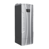
Figure 9-1 Condensate neutralizer box (see also Figures 3-3 throgh 3-10, Item 3)
A = Pipe connected to the heaters’
fl ue exhaust system
B = Condensate neutralizer box
C = Condensate drain pipe
D = Cover of the box
A = Condensate drain pipe
B = Floor drain or drain pan (Below this point there must
be a trap capable of preventing the return of sewer gas)
9 - INSTALLATION - Condensate disposal
 Loading...


