Eagle - Onboard air-data measuring system for R/C planes. Page 4
Physical overview
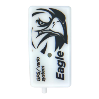
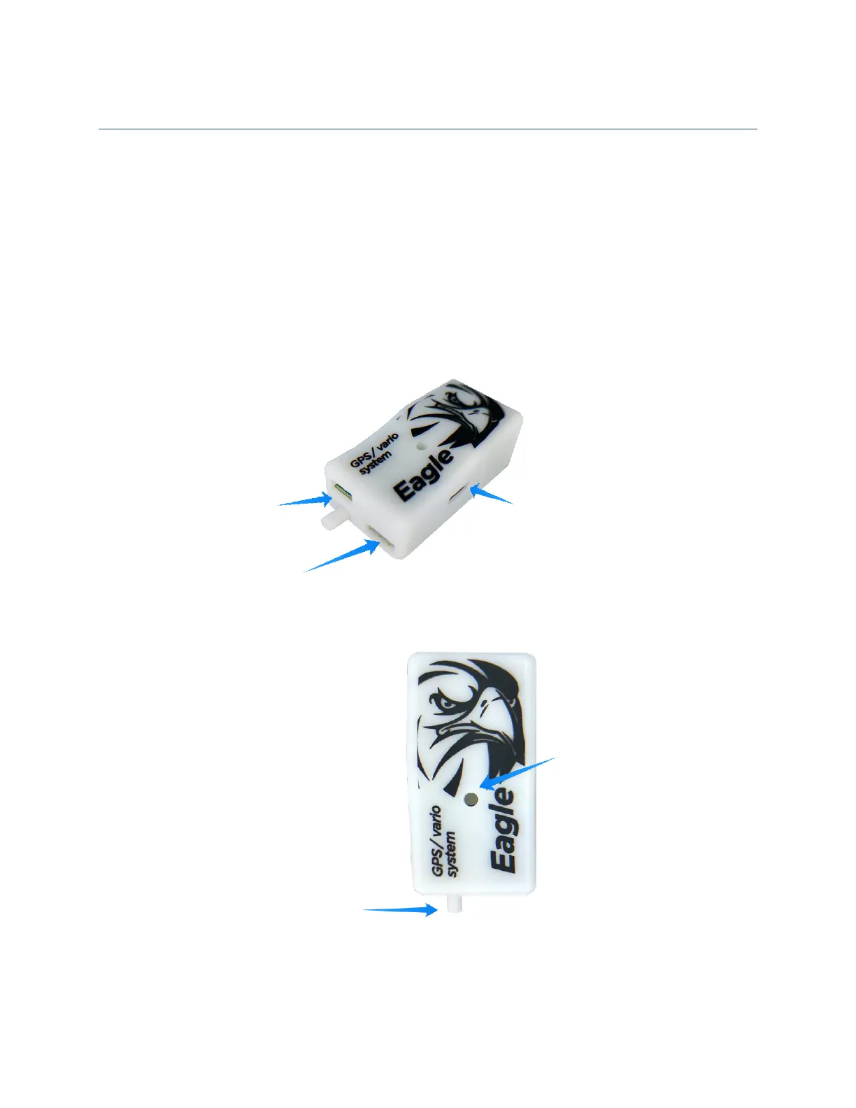
Pictures bellow are showing the Eagle unit. It has build in GPS antenna, one pressure port (Pte – total
energy compensated pressure from TEK probe) and a multi-color LED to show the status of the unit. It
also has 3 connectors. The micro USB is used for future updates, settings and flight log download. The 4
pin connector is prepared for future use (extended bus). JR 3-pin servo input is used to measure normal
PWM servo pulse or to transmit 3
rd
party telemetry protocol on it (depends on unit setting). The unit gets
power from USB or JR connector.
Important: Be careful on polarity when connecting power to the unit. Improper connection can damage
unit! Correct polarization is marked on the bottom of the unit by the servo connector!