www.SteamPoweredRadio.Com
I
I
I
I
I
I
I
I
I
I
I
I
I
I
I
I
I
I
I
I
I
Purpose
Description
Circuit
The
Type BPA-10 Antenna Tuning Equipment serves
the
double
purpose
of
matching antennas
of
widely
di-
vergent characteristics
to
either t oncentric
or
open-wire
transmission lines
and
of
suppress·ing
carrier
harmonics
on transmitters up
to
ten kilowatts
(kw)
output
.
Construction
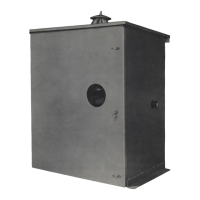
All
parts
of
this equipment
are
enclosed in a
weather
-
proof
metal housing
equipped
at
the
front
with
a
door
affording
ready
access
to
the interior. This
door
is
pro-
vided with a lock. The antenna ammeter may be read
through a circular
window
in
the
door
and
is
protected
from lightning surges
by
a short-circuiting switch, which
is
open, ted
by
means
of
a knob extending through the
side
of
the housing. A monitoring rectifier unit
*(
Ml-
7488-A)
is
contained
within
the housing
to
furnish,
if
de-
sired, audio-frequency
voltage
for
program
monitoring
and rectified carrier current
for
remote antenna current
indication.
*Ml-28902-B
only
.
Ml
-28902-A does
not
contoin
monitoring
rectifier.
The circuit
of
this antenna tuning unit essentially con-
sists
of
a single T-section low-pass filter which reduces-
the number
of
elements
to
a minimum. Referring to the
schematic
diagram,
Figure 5, there will be observed
two
series inductors (L
1,
L2
) which
are
employed
to
adjust independently the respective terminating im-
pedances
of
the transmission line and the antenna cir-
cuit. The capacitive shunt leg, which
is
common
to
the
two
branches,
is
fixed
at
a value determined
by
the
operating
frequency
of
the station.
Signal energy
for
operation
of
the monitoring recti-
fier
is
obtained from a tuned pickup coil (
L3
) which
is
coupled
to
the antenna
loading
inductor (
L2
).
This
energy
is
rectified
in
a full-
wave
circuit using an
5V4G
tube
and
the
output
is
balanced
to
ground
for
excitation
of
a monitoring
amplifier
. Terminals also
are
provided
for
connection to a remote antenna ammeter and inter-
lock
relay
located in the transmitter house. A 230-volt,
60-cycle
power
supply
is
required
for
energizing the
rectifier filament transformer (
Tl
).
Installation
Mounting
The unit
is
designed
for
mounting on a wooden
plat-
form
or
a steel
angle
cradle
by
means
of
the side flanges
at
the bottom
of
the housing. Rear mounting strips also
are
provided
to
permit mounting the unit on
two
up-
right
posts. Dimensions
are
given in the outline
drawing,
Figure 6.
Care
should be taken
at
installation
to
select a posi-
tion where the antenna lead
will
be as short as possible.
It
is
also
important
to
insure
adequate
grounding
by
connecting the housing
to
the
ground
system through a
heavy conductor
or
a
copper
bus.
R-F
Connections
The antenna lead-in post
is
located on the
top
of
the
unit,
and
provision
is
made
for
mounting a similar post
(Ml-19413-1
bowl
insulator) on the left-hand side
of
the
housing in case an
open-wire
line
is
used. Concentric
line when employed should _be
brought
in through a hole
in the bottom
of
the cabinet and connection made
to
the
upper terminal
of
coil L 1. In cases where a remote an-
tenna ammeter
is
not used, terminals
No.
5
and
No.
8
should be connec_ted
together
by
means
of
a jumper.
Remote
Metering
and
Audio
Monitor1ng
An a-c supply
of
230
volts,
60
cycles
will
be required
to
operate
the rectifying equipment
for
remote meter-
ing. The associated filament transformer
is
tapped
for
operation
at
190, 210,
230
or
250
volts
and
'should be
adjusted
to
the
tap
nearest the existing line voltage.
Terminals
No
. 2
and
No.
3
are
used
for
connection
of
the
power
supply.
Static
Drain
No
provision
for
static
drain
is
made in this unit.
If
no conductive
path
to
ground exists elsewhere, a static
drain
should be mounted across the antenna horn
gap,
or
at
some
other
suitable place.
Tower
Lighting
No
complication as
to
tower
lighting
is
introduced
as the shunt arm
is
open circuit
to
power
frequencies.
Tuning
CAUTION
-
REMOVE
THE
TRANSMITTER
PLATE
VOLTAGE
PRIOR
TO
EACH
ADJUSTMENT
OF
THE
ANTENNA
AND
TRANSMISSION-LINE
CIRCUITS.
FULL
POWER
SHOULD
NOT
BE
APPLIED
TO
THE
LINE
BEFORE
PROPER
ADJUSTMENTS
HAVE
BEEN
COM-
PLETED.
DANGEROUS
VOLT
AGES
MAY
OCCUR
THROUGH
IMPROPER
TERMINATION
AND
RESULT
IN
DAMAGE
TO
THE
LINE
AND
EQUIPMENT_
6enaral
Conditions
Although
the network used in this unit serves the
two
functions
of
impedance matching
and
antenna tuning
concurrently,
it
is
desirable
to
consider them separately.
For antenna tuning, the coil
L2
can be used
to
series-
resonate the reactive component
of
a capacitive
an-
tenna; or,
if
the antenna
is
inductive, the reactive com-
5
 Loading...