www.SteamPoweredRadio.Com
ponent' can be thought
of
as
being absorbed into the
antenna tuning coil.
In
either case, only the
resistive
portion
of
the antenna impedance
is
left,
and
the im-
pedance matching function can be regarded
as
taking
place between purely resistive impedances, inasmuch
as
the characteristic impedance
of
most lines
is
resistive.
Under these conditions, the values
of
reactance em-
ployed are determined
by
the values
of
the impedances
to be matched, with the phase shift through the network
as
-a parameter. Since the circuit
is
a section
of
a low-
pass
filter, the phase shift may be anywhere between
zero and
-180
degrees, moking possible a wide range
of
reactance values. However, it
is
not advisable
to
work
too close to the
-180
degree (or cut-off) point
of
the
section,
or
with
such
low
values
of
phase shift
that
the
second harmonic will not be sufficiently attenuated,
hence a value near
-90
degrees will usually be found
most suitable.
These
statements will become clearer
upon examination
of
the equations re'lating
to
the re-
actances
of
the arms
of
the network and the antenna
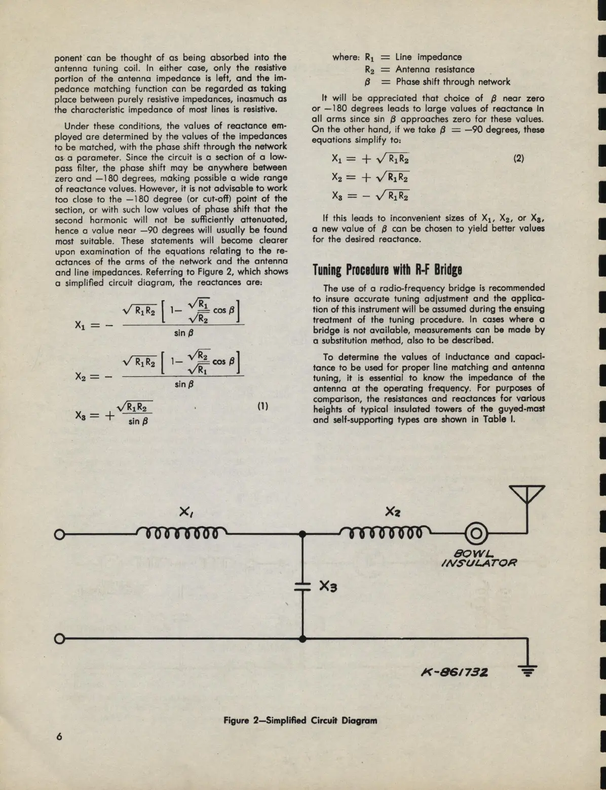
and line impedances. Referdng to Figure
2,
which
shows
a simplified circuit diagram, the reactances are:
~r
1-
~cosP]
sin
P
X2
= -
~
[
1-
v'i½
cos
P]
~
~
Xa=
+ - -
sin
P
sin
p
x,
(1)
Line impedance
Antenna resistance
=
Phase
shift through network
It will be appreciated
that
choice
of
p
near zero
or
-180
degrees leads to large values
of
reactance
In
all
arms since
sin
p
approaches zero
for
these values.
On
the other hand, if we take
p =
-90
degrees,
these
equations simplify to:
X1
=
+
~
X2=+~
Xa=-~
(2)
If this leads to inconvenient
sizes
of
X
1
,
X2,
or
Xa,
a new value
of
p
can be chosen
to
yield better values
for
the desired reactance.
Tuning
Procedure
with
R-F
Bridge
The
use
of
a radio-frequency
bridge
is
recommended
to
insure accurate tuning adjustment and the applica-
tion
of
this instrument will be assumed during the ensuing
treatment
of
the tuning procedure. In
cases
where a
bridge
is
not available, measurements can be made
by
a substitution method, also
to
be described.
To
determine the values
of
inductance and capaci-
tance
to
be
used
for
proper line matching ond antenna
tuning, it
is
essential
to
know the impedance
of
the
antenna
at
the operating frequency. For purposes
of
comparison, the resistances and reactances
for
various
heights
of
typical insulated towers
of
the guyed-mast
and self-supporting types
are
shown in Table
I.
Xz
BOWL.
INSUI..ArOR
X3
X-S6173Z
-
-
-
Figure 2-Simplified Circuit
Diagram
6
I
I
I
 Loading...