www.SteamPoweredRadio.Com
I
I
I
I
I
I
I
I
I
I
I
I
I
I
I
I
I
I
I
I
I
TABLE
I
Antenna
Height•
Self-Supporting Guyed-Mast
in
·
Electrical
Type Type
Degrees
G
R
jx
R
jx
50
7
-jlOO
8
-j220
60
9
-j
70
13
-j170
70
14
-j
25
19
-j
75
80
20
+ j
11
28
-j
28
90
40
+j
35
36
+j
0
100
60
+j
80 80
+j140
110
90
+j
90
140
+j320
120
175
+j
80
220
+J500
130
190
+J
15
370
+J600
140
165
-j
70
660
+j480
150
130
-j
85
1100
+j
0
160
82
-J
55
550
-J250
170
60
-J
25
280
-J450
180
40
-J
5
180
-J500
190
28
+J
25
120
-J430
200
23
+J
50
80
-J400
• Height
in electrical
degrees
=
Height
in
feet
X
frequency
in
kilocycles
X
1.016
X
10-0
X
360.
Substitution
of
the resistance components
of
line
and
antenna impedances in the equations (
1)
gives the values
of
X
1
,
X
2
and
X
3
necessary
for
the impedance m·atch-
(ng function. Examination
of
the reactive components
indicates the reoctonce necessary
for
tuning. For ex-
ample, suppose
we
hove a 60-ohm line
and
a 120-
degree antenna
with
175 ohms
of
resistance
and
+j80
ohms
of
reoctonce. Substitution
of
the values
60
and
175 ohms in equations (2) gives the
value
of
102.5
ohms
for
X
1
,
X2
and
X3.
To tune
out
the antenna reoctonce in this case,
it
is
only
necessary
to
assume
that
this reoctonce
is
a
port
of
the required
value
of
X
2
.
Subtracting the
80
ohms
of
antenna reoctonce from 102.5 ohms leaves 22.5 ohms
to
be
obtained
in the coil
L2
.
When
the other arms
of
the network hove been adjusted to the
proper
v
alue
of
the 102.5 ohms, there will exi
st
a condition
of
im-
pedance match between the line and the antenna re-
sistance
and
the antenna reoctonce will hove been
removed
as
a cause
of
loss
.
In
making these adjustments, the line should be di
s-
connected
and
_ the impedance
bridge
connected across
the input terminals
to
determine when the desired value
of
60
ohms hos been obtained. When measurements
show
that
the input impedance
of
the tuner with the
antenna connected
is
60
ohms resistive, the line may be
reconnected
for
a final check before turning on .full
power
.
Calculations
of
the current in the capacitive branch
ore
made to insure
that
the
rot
ing
of
the capacitor
is
not exceeded. Proper capacitors
are
supplied on the
basis
of
information received with the
order
.
To
enable
intelligent estimates
to
be mode
of
the
inductances
obtained
by
topping
down on coi
ls
L 1
and
L2,
it should be mentioned
that
their maximum induct-
ance
is
120 microhenries.
Tuning
Procedure
Without
R-F
Bridge
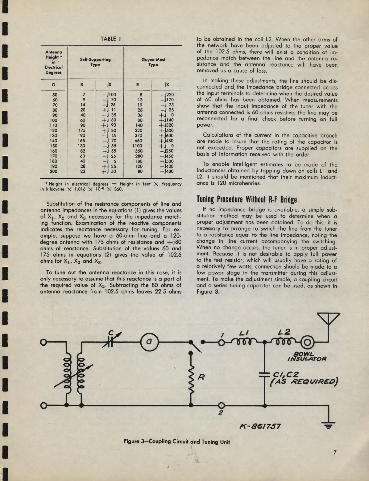
If
no impedance
bridge
is
available,
a simple sub-
stitution method
may
be used
to
determine when a
proper
adjustment has been obtained.
To
do
this, it
is
necessary
to
arrange
to
switch the line from the tuner
to
a resistance equal
to
the line impedance, noting the
change in line current accompanying the switching.
When
no change occurs, the tuner
is
in
proper
adjust-
ment. Because it
is
not desirable
to
apply
full
power
to
the test resistor, which will usually have a roting
of
a relatively
few
watts, connection should be made
to
a
low
power
stage in the transmitter during this adjust-
ment.
To
make the adjustment simple, a coupling circuit
and a series tuning
capacitor
con be used, as shown in
Figure
3.
LZ
c1,,c2
(AS
REQUIRED}
2
K-86/757
Figure
3-Coupling
Circuit and Tuning Unit
7
I
 Loading...