www.SteamPoweredRadio.Com
With
'
the
switch in
the
resistor position, capacitor C
can be tuned
for
a maximum current reading in meter
G.
Then, on switching
to
the tuner input, the direction
in which capacitor
C
must
be
turned
to
increase the
current
again
to
a maximum indicates the sign
of
the
reactance in the antenna circuit. If
the
capacitance must
be increased, the
load
is
capacitively reactive;
if
the
capacitance must
be
decreased, the
load
is
inductively
reactive;
if
no change
is
necessary,
the
load
is
resistive.
Similarly, if the current reading
at
resonance
is
greater
than before, the
load
resistance
is
less
than
Z
0
;
if
that
reading
is
less
than before, the
load
resistance
is
greater
than
Z
0
;
if
there
is
no change, the
load
resistance
is
equal
to
Zo-
CAUTION-Remove
unused jumpers.
This method may be used
to
determine unknown re-
sistances simply
by
using a
calibrated
test resistor; like-
wise,
unknown reactance values may be determined
by
using a
calibrated
condenser
at
C.
Final
Check
Upon completing the tuning procedure as outlined in
the preceding paragraphs, the adjustments should be
checked before full power
is
applied
to
the line
and
antenna. The recommended method
of
check
is
de-
scribed in the
following
paragraph.
With
the measuring equipment disconnected from the
· tuning unit, attach the transmission line
and
insert a
low-range thermal milliammeter in the ungrounded side
at
each end of the line.
Apply
sufficient
power
to
pro-
vide a
readable
deflection on each meter and note the
current values. These values should
agree
within 15
per
cent when the tuning adjustment has been correctly per-
formed. Under
such
conditions, full
power
may be
ap-
plied
to
the line
after
removing the millammeters.
Upon
application
of
fvll
power, the current through
each
of
the tuning capacitors
(Cl,
C2) should be
measured under conditions
of
full modulation. The
maximum permissible current values
for
these capacitors
at
three nominal frequencies
are
shown on the name-
plates.
At
intervening frequencies, the maximum values
will
be
approximately
proportional
to
those listed. If
such
currents
are
found
to
be
excessive, the capacitors
should
be
rearranged in the circuit.
Remote
Metering
Equipment
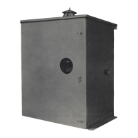
The antenna tuning unit embodies the necessary
equipment
to
enable the installation of a remote meter
for
measuring antenna current and also furnishes audio-
frequency energy
for
operation
of
a monitoring ampli-
fier. The method
of
remote antenna-current indication
as
outlined herein has been approved
by
the Federal
Communications Commission.
The remote meter should require 25
to
50
ma
direct
current
for
full-scale deflection and should have a scale
corresponding
to
that
of the antenna ammeter (M
1)
.
It should be equipped with a shunt adjusted
so
that
the
deflections
of
both meters
are
identical.
In
most cases, a
5-ohm
variable
shunt will be satisfactory
for
this pur-
pose.
As
shown
by
the schematic
diagram
(Figure 5), ter-
minals No.
5
and
No
.
8
are used
for
connection
to
the
remote meter and transmitter interlock relay. Sufficient
output
for
proper
deflection of the remote meter may
be obtained
by
adjusting the coupling between the an-
tenna
loading
inductor (
L2
} and the monitoring pick-up
coil (
L3
} and
by
tuning the latter
to
the carrier fre-
quency. A
wide
tuning range
is
afforded
by
the six
taps on the pick-up coil and
by
the
use
of
two
capaci-
tors (C4, C5) whi
ch
may be employed singly, in series,
or
in
parallel.
Jumpers are provided
to
facilitate inter-
connection of these capacitors.
Maximum output will be secured
as
the pick-up coil
is
tuned
to
resonance. It
is
not advisable, however,
to
approach
resonance
too
closely since the increasing
selectivity of this circuit
will
seriously impair the audio-
frequency response characteristic.
At
resonance, the re-
sponse
at
10,
000
cycles will be
down
approximately
4
db
. Under no conditions should the current through the
series
resistors (
Rl,
R4)
be
allowed
to
exceed
75
ma
d.
c.
When an
audio
moni
tor
is
to
be used,
an
output
level of
approximately
+
17 dbm
is
available
from
this source, the circuit
of
which
is
balanced
to
ground
and may be used to feed a 500-ohm
load
.
The
load
in
this case must be
capable
of
handling 25
ma
of
direct
current. It
is
desirable, therefore,
to
feed a 20,000-ohm
or
greater
bridging
load
. If the monitoring ampfifier has
only
a 500-ohm input, a 20,000-ohm carbon resistor may
be inserted in series with the 500-ohm transformer.
Under this condition, the direct-current
flow
is
negligible
and the output level from the rectifier
is
reduced
to
-1
dbm
at
5-kw operation and to
-7
dbm
at
1-kw opera-
tion.
Maintenance
The antenna ammeter shorting switch
(Sl)
should
be
kept closed except when readings
are
being taken.
All
connections, especially the coil connector clips,
8
should be inspected
regularly
to
insure tightness and
thus
avoid
undue heating
at
such
points. Screens and
ventilation openings should be unobstructed
to
permit
free circulation
of
air.
I
I
I
I
I
I
 Loading...