ENGLISH
8
WARNING: do NOT connect the BLACK wire (8 ) to a 100 / 70 V line (as
this may damage the loudspeaker and / or the amplier)!
Notes:
- the loudspeaker iNput voltage (vd) shall correspoNd to the amplifier output voltage (va).
- the sum of NomiNal power values (pd x N) of all loudspeakers coNNected to the liNe
shall Not exceed the amplifier power (pa).
100 V CONSTANT VOLTAGE LINE
When connecting a BS 2620 to a 100 V constant voltage line, its wires (to be
linked) shall be chosen according to the desired power rate (as indicated in
the following table):
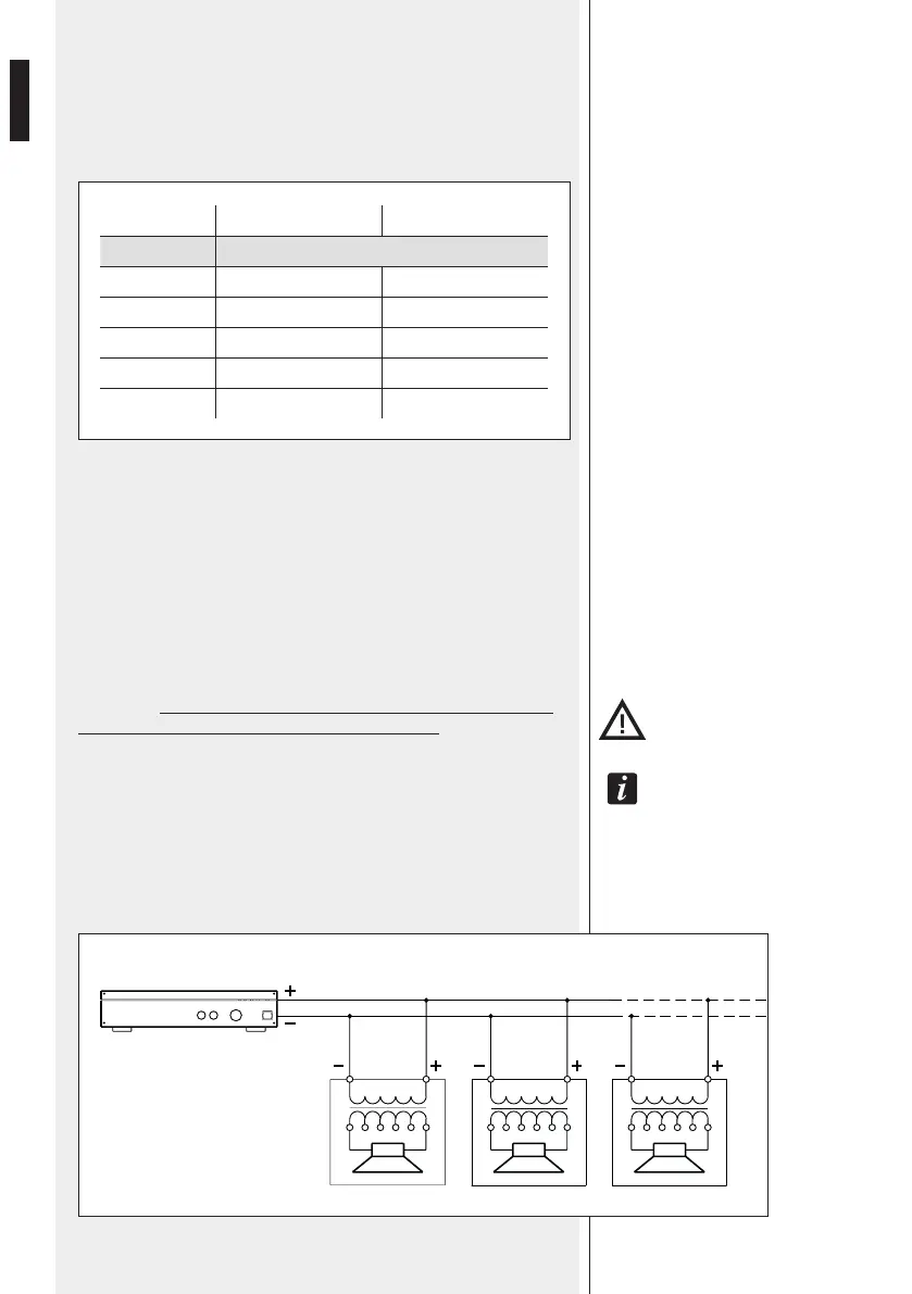
COLOUR POWER IMPEDANCE
RED Common wire (+, positive)
WHITE 20 W 500
BLUE 15 W 666
YELLOW 10 W 1 K
GREEN 5 W 2 K
BROWN 2.5 W 4 K
Connect the amplier positive output (+, 100 V, a) to the loudspeaker
common RED wire.
Connect the amplier negative output (–, 0, COM, b) to the other
loudspeaker wire (white, blue, yellow, green or brown) chosen according to
the desired power rate. Insulate all unused wires.
Before turning the amplier on, check connections again.
If connecting to a 70 V line, its power rate will be halved.
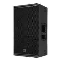
AMPLIFIER
Pa = Amplier power
Pd = Speaker power
n = Number of speakers
Vd = Speaker input voltage
Va = Amplier output voltage
Pa > Pd x n Va
Vd = Va Vd = Va Vd = Va