9
ENGLISH
LOW IMPEDANCE CONNECTION (8 )
Connect the amplier positive output to the loudspeaker common RED wire.
Connect the amplier negative output to the loudspeaker BLACK wire.
Insulate all unused wires.
Before turning the amplier on, check connections again.
Max. power is 20 W.
Notes:
- the siNgle loudspeaker impedaNce or its total value (wheN several loudspeakers are
liNked iN series / parallel) must Not be lower thaN the amplifier output impedaNce.
- a loudspeaker total impedaNce equal to the amplifier output oNe permits to get the
maximum deliverable power (but aN higher loudspeaker impedaNce eNtails less power).
- the total loudspeaker power shall be adequate for the maximum deliverable power
of the amplifier.
- the loudspeaker liNe shall be as short as possible (for loNg distaNces, it may be
Necessary to use cables with large cross-sectioN wires).
- the impedaNce of a siNgle loudspeaker is 8 Ω; the total impedaNce of the parallel of
2 loudspeakers is 4 Ω (impedaNce = 8 / loudspeaker Number).
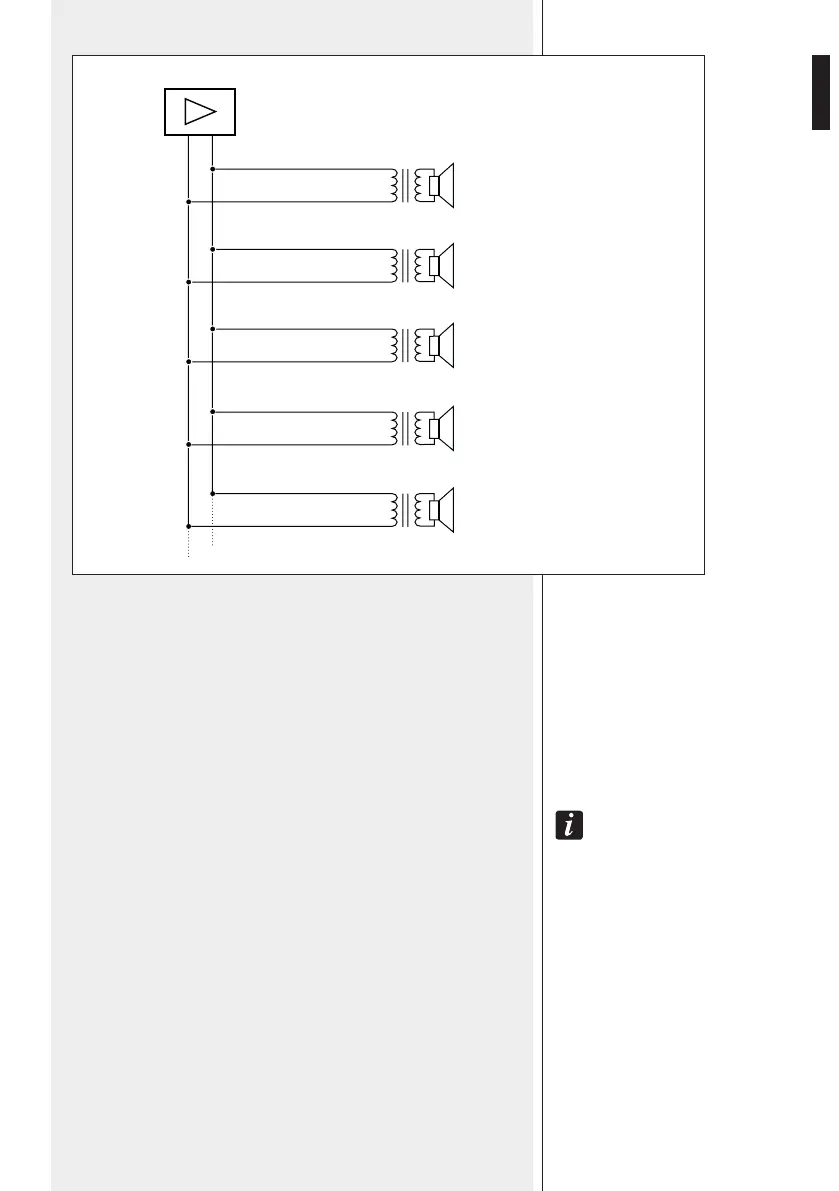
EXAMPLE: 100 V LINE CONNECTIONS AND TAPPING
0 100 V
100 V - 20 W
0
Loudspeaker set to 20 W
100 V - 5 W
0
Loudspeaker set to 5 W
100 V - 2.5 W
0
Loudspeaker set to 2.5 W
100 V - 15 W
0
Loudspeaker set to 15 W
100 V - 10 W
0
Loudspeaker set to 10 W
Red
White
Red
Green
Red
Brown
Red
Blue
Yellow
Red