7
ENGLISH
The fifth screw terminal (red wire) allows the loudspeaker connection to an
amplifier low impedance output (usuallly 4 – 8 Ω).
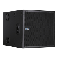
Remove the loudspeaker bottom cover (by unscrewing the 2 screws) to access its
terminal strip. The cable shall pass through the loudspeaker rear hole.
REAR HOLE
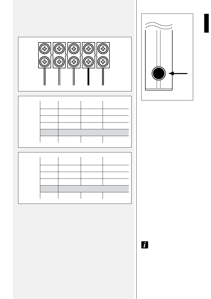
CS 3041 COLOUR VOLTAGE POWER IMPEDANCE
green 100 V 10 W 1000
Ω
white 100 V 15 W 667 Ω
yellow 100 V 20 W 500 Ω
black common
red 20 W 16 Ω
CS 3082 COLOUR VOLTAGE POWER IMPEDANCE
green 100 V 10 W 1000 Ω
white 100 V 20 W 500 Ω
yellow 100 V 30 W 333 Ω
black common
red 30 W 8 Ω
100 V CONSTANT VOLTAGE LINE:
Connect the amplifier output marked with ‘0’, ‘b’ or ‘COM’ to the
loudspeaker common input (black wire).
Connect the amplifier 100 V output (terminal marked with ‘100 V’ or ‘a’)
to one (only) of the 3 loudspeaker 100 V inputs (according to the chosen
power).
Note: do Not coNNect the 100 V liNe to the loudspeaker low impedaNce iNput
(red wire).
AMPLIFIER WITH LOW IMPEDANCE ( 4 – 8 Ω) LOUDSPEAKER
OUTPUTS:
Connect the amplifier ‘–’ output to the loudspeaker common input (black wire).
Connect the amplifier ‘+’ output to the loudspeaker low impedance input
(red wire).
AMPLIFIER WITH LOW
IMPEDANCE ( 4 – 8 Ω)
LOUDSPEAKER OUTPUTS
100 V CONSTANT
VOLTAGE LINE
GREEN
WHITE
YELLOW
BLACK
RED