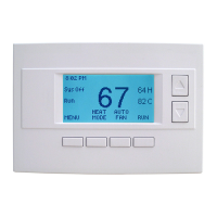
Thermostat Setup: Heat Pump HVAC Systems
To set the HVAC system type, go to the Thermostat Info screen Setup or the Installer Settings menu
(a hidden screen – go to the main menu screen and press and hold the center two buttons for 5 seconds)
In the Installer Settings Menu, Select System Settings then select Mechanical Settings and set the following:
1. Type. Set the HVAC System Type: set to Heat pump
2. Fan Type. Automatically set for Heat Pump systems. Ignore this setting
3. C/O type. Change Over valve energizes either with cool calls or with heat calls. You must configure the
thermostat’s changeover valve setting to work correctly with your HVAC system. Check your system information to
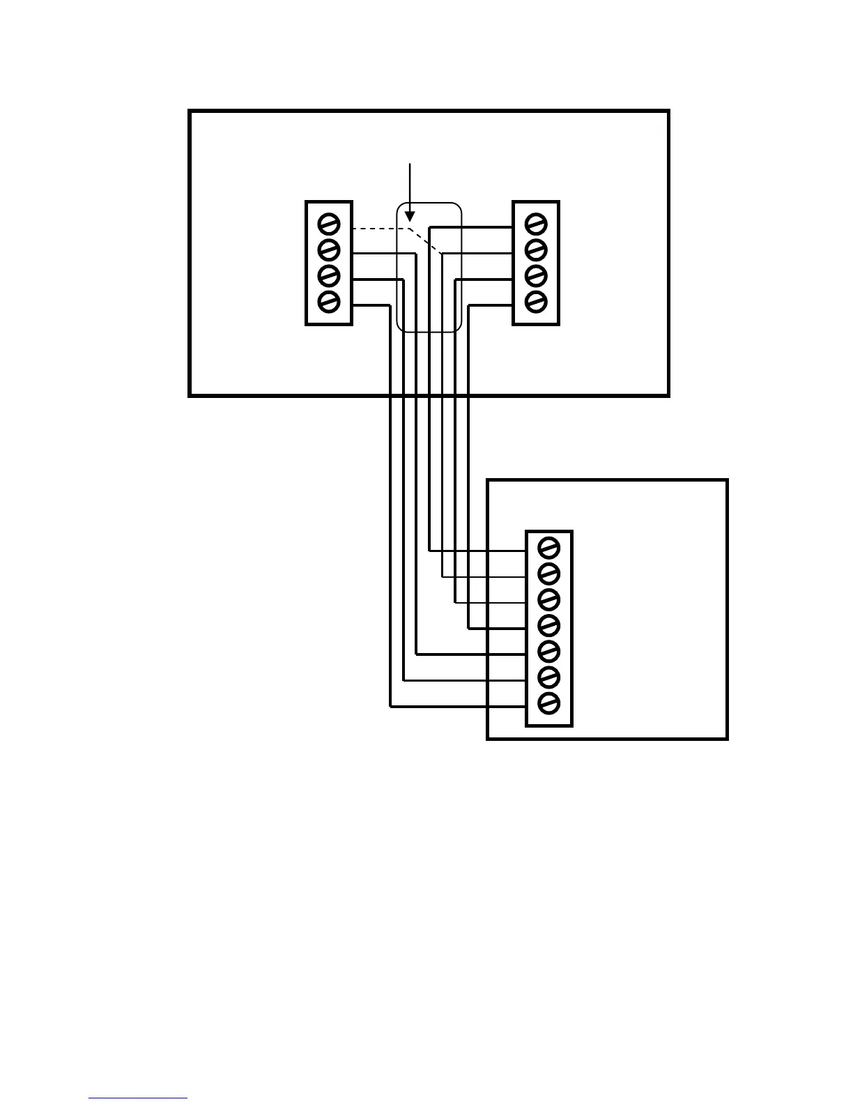
be sure. Note the color of the wire (Orange or Brown) and to which terminal (O or B) on the old thermostat the
wire was connected to. No matter what the old stat connection was, connect the wire to the W2/O terminal on the
TZ45. The setting for C/O type will set the correct system operation.
For change over with cool systems (old stat O terminal/orange wire) = set to w/cool (most common
type and default setting)
For change over with heat systems (old stat B terminal/brown wire) = set to w/heat
Note: If you get cooling when you expect heating, change the C/O type to the opposite setting
4. 2nd Stage Heat. Enable second stage heating outputs
If you have a single stage heating system, leave this set to N
If you have a 2 stage heating system, set to Y to enable.
5. Aux Heat (HP). If you have auxiliary heat strips, set this to Y (default setting), if not, set to N
6. 2nd Stage Cool. Enable second stage cooling outputs
If you have a single stage cooling system, leave this set to N.
If you have a two stage cooling system, set to Y to enable.