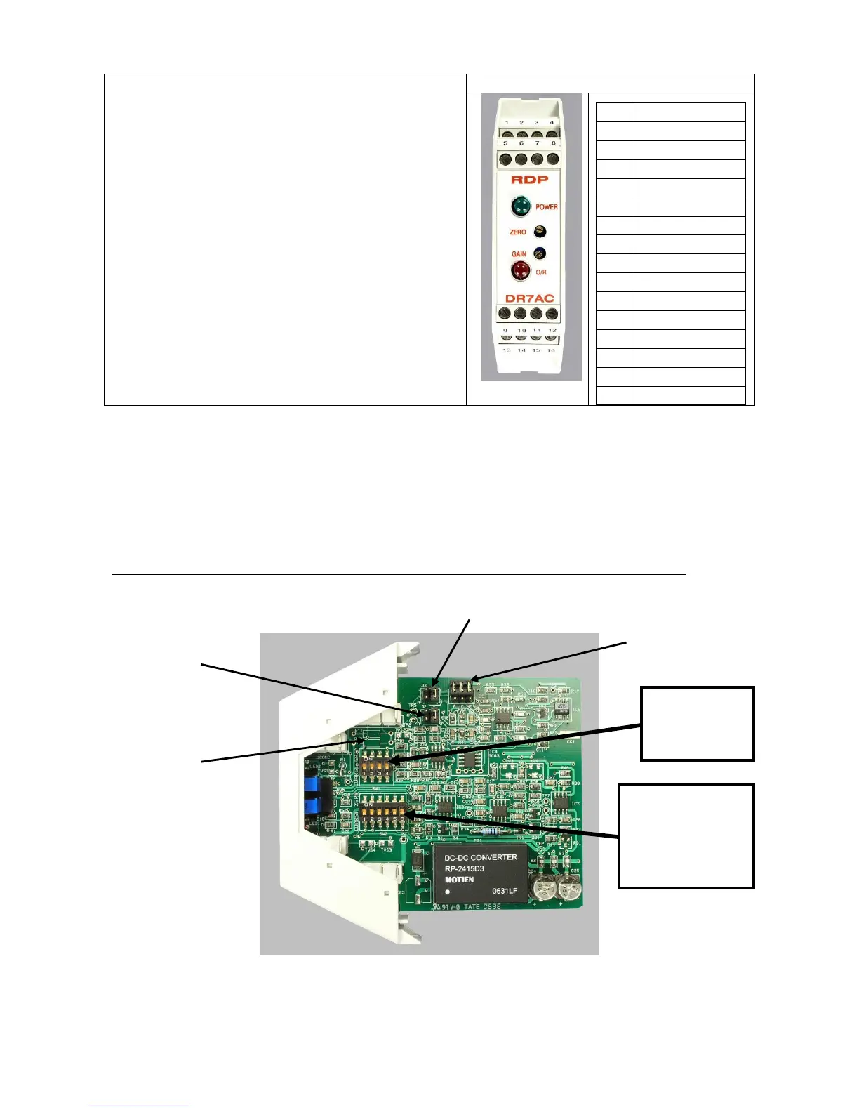
Transducer, supply and output connections are
made by 4 x 4 way screw-clamp terminals as
shown in Fig 1.
To reverse output polarity, reverse signal
hi/signal lo. Voltage output is between Volts Out
and common, current output is between current
out and common. Output common is internally
connected to Excitation Lo.
WARNING: INCORRECT SUPPLY
CONNECTION, e.g. CONNECTING SUPPLY
WIRE TO OUTPUT (O/P) MAY DAMAGE THE
UNIT AND INVALIDATE THE WARRANTY.
To access internal controls the front part of the DR7AC case needs to be removed. To do
this, use a small screw driver to gently press in the clips behind terminal 1-4 and 13-16. At
the same time pull forward the front of the case. The front of the case and pcb assembly
should now slide forward.
It will usually only be necessary to make changes to Gain and Zero controls.
To put case back together, gently slide pcb assembly into case guide slots. Ensure pcb
earth pad CG1 is lined up with the earth clip inside the case, and push back until the front
of the case clicks back into place.