3.5 Zero Input
SW2 toggle 6 which, when switched to ON, zero’s the signal, input voltage to the amplifier
irrespective of transducer position. This enables a true amplifier zero to be realised.
3.6 Fine Zero (On front panel, labelled ZERO)
A screwdriver-adjusted, 25-turn potentiometer allowing adjustment of output zero by ±1V
to ±4V depending on Fine Gain setting. Used with 3.3 will provide up to 100%
suppression.
3.7 Over-Range Indicator
A red lamp that indicates when the demodulator input exceeds the linear range.
3.8 Excitation Voltage
Units are normally supplied with 1V excitation. This can be changed to 3V by changing J3
to B-C.
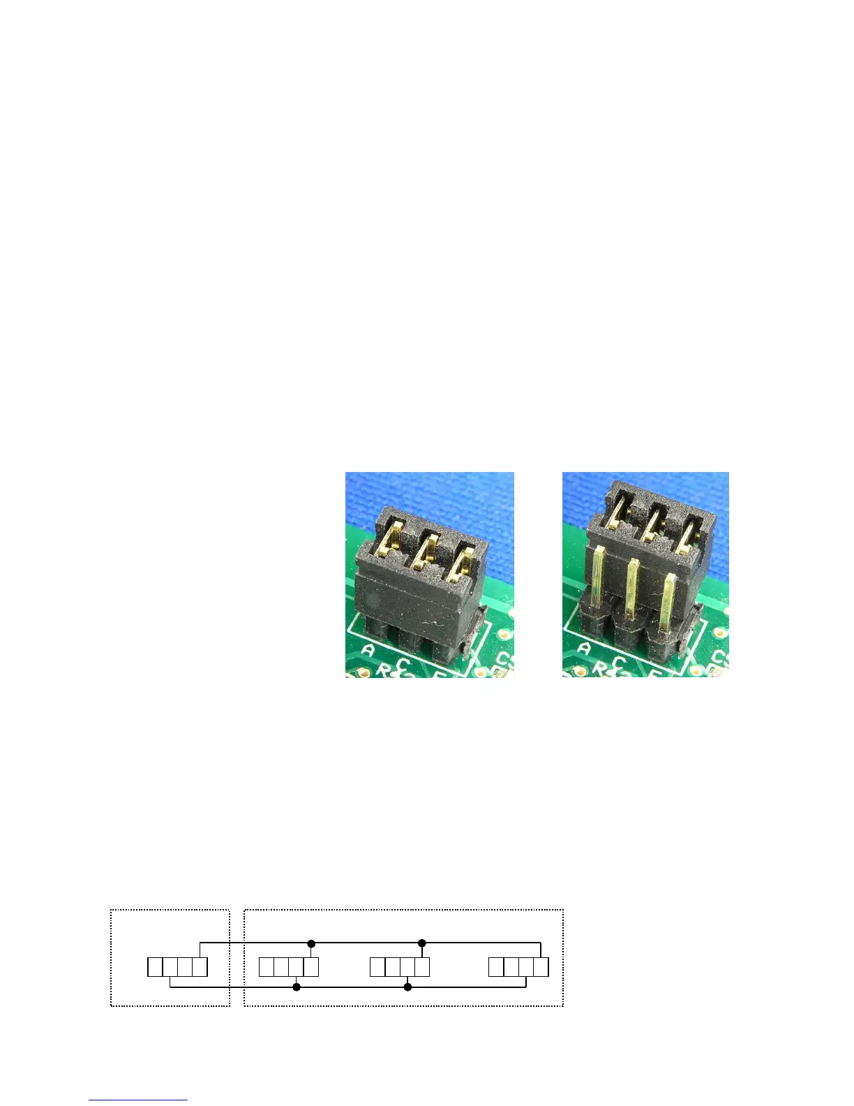
3.9 Excitation Frequency
If necessary, excitation
frequency can be changed
by moving J1 as shown.
Figure 2 shows the location
of J1.
Other excitation frequencies
are available if stated when
ordering.
3.10 Master/Slave
The unit may be configured as a master oscillator or slave oscillator by the setting of J2.
For Master oscillator (Factory Default) link J2 B-C
For Slave units link J2 A-D
Link terminal 6 on the MASTER unit with terminal 7 on the SLAVES and link terminal 8 on
all units as shown below:
Fig 5. Master/Slave Connections