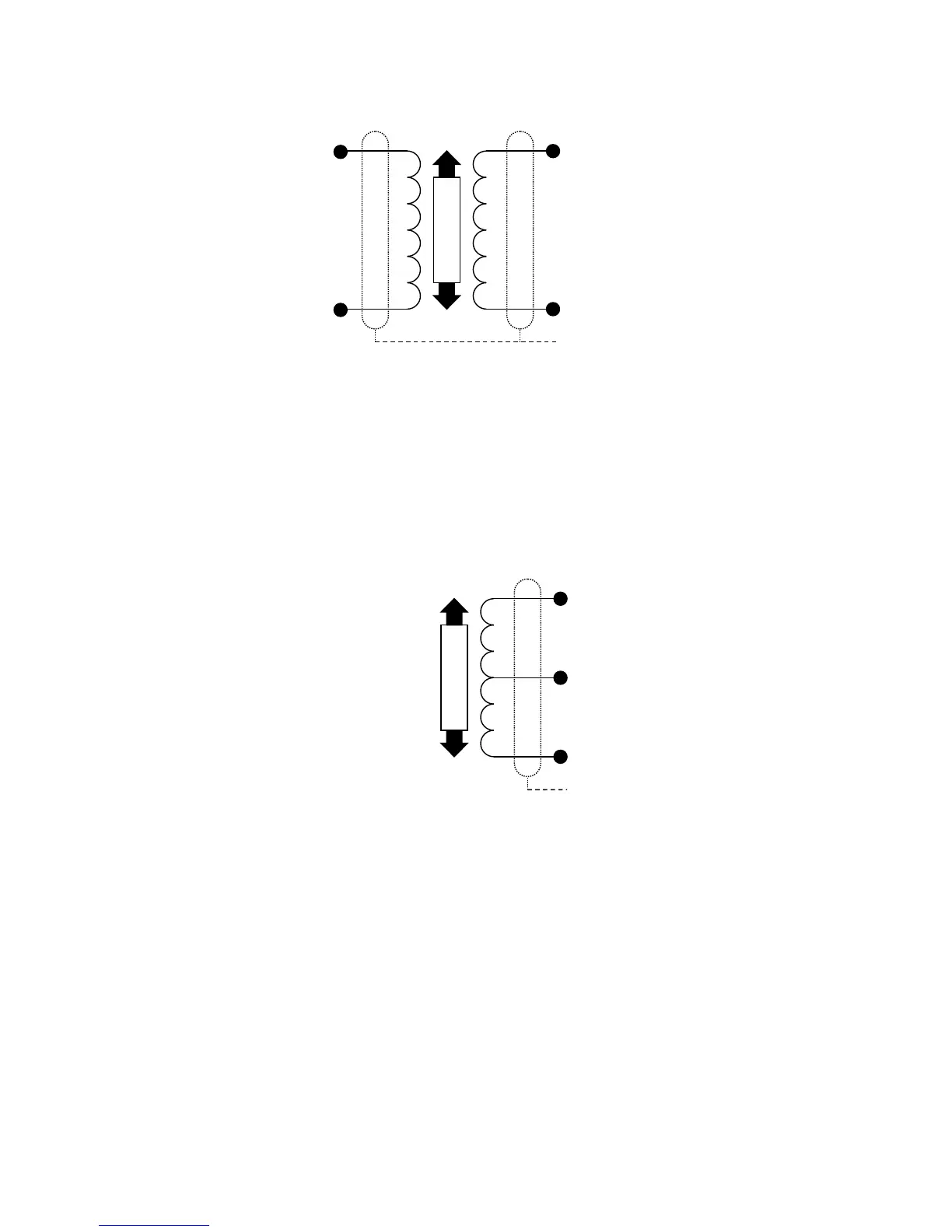
See fig. 1 for pin designations.
Most RDP LVDT transducers also have a BLACK wire. This is not required with the
DR7AC amplifier and should be insulated and left unconnected.
If the above configuration does not give the required output phase (i.e. the output rises
for outward transducer movement instead of falling); reverse signal high and signal low
connections.
In addition to these connections, it is necessary to add two bridge completion resistors
to compensate for the fact that the transducer is only half bridge. For RDP transducers,
the resistors should be 1k Ohms, high stability. These should be mounted in R11 and
R12 locations, as shown in Fig. 2.
If when connected, the phase of the amplifier output is not as required (for example, an
inward moving armature causes a rising amplifier output when a falling output is
required) then reversing the excitation high and excitation low wires will correct this.