Do you have a question about the Real Flame Captiva 900 and is the answer not in the manual?
Covers defects in firebox/parts and lists exclusions.
Registration requirement, claiming procedure, and liability limits.
Precautions for primary safety glass and hot panel surfaces.
Guidelines on keeping flammables away and avoiding aerosols.
Heater type, warranty void conditions, cautions, and location advice.
Specific warning for installation on combustible flooring materials.
Instructions for removing the appliance's glass door.
Steps for positioning logs and coals in the firebox.
Instructions for placing pebbles in the firebox.
Final checks to be completed after installation.
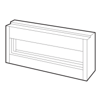
Diagrams and tables showing the unit's overall dimensions.
Dimensions specific to the 4-sided and 3-sided trims.
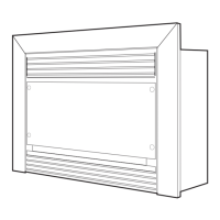
Diagrams and tables showing the unit's overall dimensions.
Dimensions specific to the 4-sided and 3-sided trims.
Overall dimensions for timber frame installation.
Options for vertical and horizontal flue terminations.
Visual guides for installing in a timber frame.
Table detailing required frame opening dimensions.
Table specifying minimum clearances from combustible materials.
Clearances and requirements for vertical flue terminations.
Guidance on selecting the location for flue termination.
Important notes on flueing clearances and component integrity.
Essential tests like gas leaks, pressure, and operation checks.
Crucial safety steps before servicing, like power isolation.
Steps to remove doors and plates for access.
Procedures for removing specific internal components like burner and modules.
Procedures for removing remaining components like valve and fan.
Steps for reassembly and critical gas leak verification.
Visual identification of key parts like gas valve and remote control.
Identification of sparkers and sensors.
Locations for inlet and outlet gas pressure testing.
Points for adjusting high and low gas pressures.
Explanation of reference symbols used in the regulations.
Table detailing required clearances for flue terminals.
Explanations and specific restrictions for clearances.
Functionality, battery requirements, and optimal placement advice.
On/off operation, factory features, and initial time/day setup.
Explanation of different temperature control modes.
Overview of programming periods and starting the process.
Steps to select specific days for program settings.
Setting start times and temperatures for programmed periods.
Procedures for factory reset and thermostat ID teaching.
Important warnings regarding auto mode operation and extended absences.
Table detailing dimensions for marble hearth and margin sets.
Step-by-step procedure for installing marble margins.
Table showing dimensions for various mantelpiece models.
Diagrams illustrating Captiva flush and boxed mantel installations.
Diagram showing Printed Circuit Board connections.
Diagram illustrating ignition and fan motor control circuits.
Contact information for the main office and factory.
Contact details for various regional showrooms across Australia.
| Brand | Real Flame |
|---|---|
| Model | Captiva 900 |
| Category | Heater |
| Language | English |