Do you have a question about the Real Flame ACCENT 800 and is the answer not in the manual?
Covers firebox and parts warranty periods, coverage, and conditions for repairs or replacements.
Procedure for registering the appliance to receive warranty benefits via website or mail.
Lists conditions that void the warranty, such as improper use, storage, or maintenance.
Defines warranty limitations, excluding consequential loss or damage to property/persons.
Instructions on how to make a warranty claim, including required proof of purchase.
Specifies that installation must be performed by an authorized person following manufacturer's instructions.
Highlights essential safety notices, including warnings about hot surfaces and supervision.
Advises on the recommended frequency for servicing the gas fire.
States that electrical cord replacement must be handled by qualified personnel.
Details the model, gas type, injector size, and gas consumption (Mj/hr) for the appliance.
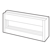
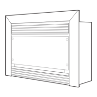
Provides technical drawings showing the overall size and key measurements of the heater.
Guidance on choosing a suitable location for the appliance, requiring supervision.
Specifies minimum safe distances from the appliance to combustible materials.
Requirements for adhering to Australian gas and electrical installation standards.
Details on flue pipe length, bends, and materials allowed for installation.
Ensures flue terminals are not recessed and are clear of obstructions for safe venting.
Details the required gas pipe connection size (15mm compression union).
Specifies the need for a 3 Pin 10 Amp GPO plug.
States the electrical power requirements: 230V 50Hz 0.55Amp.
Explains the symbols used in the flue termination clearance diagram.
Table showing required clearances for flue terminals under various conditions.
Provides additional notes and clarifications for flue terminal clearance requirements.
Instructions for setting up the external wall mounted fan terminal unit.
Guidance on installing the fan terminal module and running flues with clearances.
Steps for cutting and connecting the flue pipes to the appliance.
Specifies the type of silicone sealant recommended for flue connections.
Detailed instructions on applying sealant to flue connection spigots.
Steps for sliding flue onto spigot, tightening clamps, and checking seals.
Guidance on clipping flues to provide adequate support.
Instructions for connecting the flues to the wall mounted fan terminal.
Instruction to remove the cover from the fan terminal unit.
Steps for cutting exhaust and air intake flues to length for wall exit.
Instructions for feeding the power cable through the wall.
Ensuring flue ends are burr-free and round for proper connection.
Applying sealant around the flue connection plate spigot.
Sliding flue onto spigot, tightening clamp, and verifying seal integrity.
Feeding the air intake flue pipe and fitting retaining screw.
Positioning and affixing the fan terminal to the wall, sealing gaps.
Instruction to attach the front cover to the appliance.
Specifies the required dimensions (A, B, C, D*) for timber frame construction.
General guidelines for correctly locating and positioning the fire media.
Step-by-step instructions for arranging the logs for optimal appearance.
Specific instruction for inserting and positioning the rear log.
Specific instruction for inserting and positioning the front log.
Specific instruction for inserting and positioning the third log.
Specific instruction for inserting and positioning the fourth log.
Specific instruction for inserting and positioning the fifth log.
Specific instruction for inserting and positioning the sixth log.
Specific instruction for inserting and positioning the seventh log.
Specific instruction for inserting and positioning the eighth log.
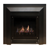
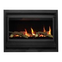
Shows the completed arrangement of all logs in the firebox.
Ensure all media is correctly installed before proceeding.
Connect the appliance to the gas supply and electrical power.
Install the firebox door securely.
Perform checks to ensure there are no gas leaks.
Connect the powerflue module loom to the fan control unit.
Execute the steps for the initial lighting of the appliance.
Verify burner and inlet supply pressures are correct.
Test the appliance for carbon monoxide (CO) leakage.
Instruction to temporarily turn off the appliance.
Install the decorative trim around the appliance.
Provide necessary operating and safety instructions to the owner.
Educate the owner on how to operate the fireplace safely.
Guide the owner on how to safely isolate the appliance in emergencies.
Immediate actions if a gas smell is detected: turn off and contact a professional.
Do not operate if submerged in water; contact a service technician.
Warning against burning solid fuels or placing materials near the fire.
Note that luminous flames and carbon deposits may occur during operation.
Allow a 2-minute wait before re-igniting if the appliance failed to ignite.
Guidance on contacting professionals for issues like noisy fans or unusual flames.
Overview of the remote control's functions and capabilities.
Explanation of the symbols and information shown on the remote's LCD screen.
Specifications including supply voltage (AAA batteries) and radio frequency.
Caution that metal placement near the receiver can reduce signal range.
Turn off the main gas supply before installing or maintaining the receiver.
Turn off gas supply before removing or replacing transmitter batteries.
Turn off the IFC device using the ON/OFF switch if the remote malfunctions.
Switch off the IFC device by removing the power plug for installation/maintenance.
Procedure for synchronizing the remote control transmitter with the appliance receiver.
How to check and set the temperature display between Celsius and Fahrenheit.
Instructions for activating the appliance using the remote control's ON/OFF button.
Instructions for deactivating the appliance using the remote control.
How to increase or decrease flame levels using the up and down arrow keys.
Setting the appliance to maintain a desired room temperature.
Automatic flame adjustment based on room temperature and set point.
Indicates that fan speed control is not available for this appliance.
Indicates that remote dimmer control for light is not supported.
Indicates that split flow control functionality is not available.
How to select between Continuous Pilot Ignition (CPI) and Intermittent Pilot Ignition (IPI).
How to activate and deactivate the key lock to prevent unsupervised operation.
How the transmitter indicates low battery power.
Indicates that remote auxiliary relay control is not supported on this fire.
Troubleshooting steps for when the remote control has no effect.
Diagnosing and resolving issues where the fire cuts off or won't relight.
Addressing issues with the flame appearing too low or excessively high.
Solutions for smells from paint curing or potential firebox door leaks.
Troubleshooting a noisy or non-functioning room air fan.
Resolving the issue where the pilot light remains constantly illuminated.
Step-by-step guide for authorized technicians to reprogram the remote to the heater.
Identifies the specific button on the receiver for the reprogramming process.
Details available fault codes for the Gas Valve controller and the remote.
Advice to consult dealers or technicians for persistent operational issues.
Provides a detailed schematic of the electrical connections for the SIT Proflame 2 IFC control board.
Requirement to change valve, pilot injector, and main burner injector for gas type.
Detailed instructions for safely removing and replacing the gas valve.
Procedure for changing the pilot assembly and main burner injector.
Lists key appliance parts with corresponding images for easy identification.
Contact details for Glen Dimplex Australia Pty Ltd's main office and factory.
Contact information for showrooms located in Richmond, Dandenong, and Geelong, VIC.
Contact information for showrooms in Chatswood and Miranda, NSW.
Contact details for the Adelaide, SA showroom.
Contact details for the Milton, QLD showroom.
Contact details for the Osborne Park, WA showroom.
Contact details for the Fyshwick, ACT showroom.
Contact details for the Ulverstone, TAS showroom.
| Model | ACCENT 800 |
|---|---|
| Fuel Type | Electric |
| Heating Capacity | 400 sq ft |
| Voltage | 120V |
| Adjustable Thermostat | Yes |
| Overheat Protection | Yes |
| Remote Control | Yes |
| Material | Metal and Glass |
| Flame Effect | Yes |
| Type | Electric Fireplace |