EasyManua.ls Logo

Real Flame 700 User Manual

Real Flame 700
51 pages
To Next Page IconTo Next Page
Page #1 background imageLoading...
Page #1 background image
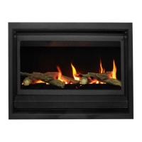
INSPIRE FLAME EFFECT SPACE HEATER
MODELS 700/900/1100
INSTALLATION & OPERATING MANUAL
The Inspire space heater is suitable to be installed into a frame out installation.
Designed to operate on Natural gas and LPG gas. Approval no.GMK 10528
Version 10A

Questions and Answers:

Real Flame 700 Specifications

General IconGeneral
BrandReal Flame
Model700
CategoryHeater
LanguageEnglish

Summary

WARRANTY INFORMATION

Warranty Details

Details the warranty coverage for defects in the firebox and gas burner parts.

Warranty Registration Process

Instructions for registering the warranty on the website or via mail.

Warranty Exclusions

Lists conditions under which the warranty is not applicable.

Limit of Liability

Defines the extent of Glen Dimplex's liability under the warranty.

Claiming Under Warranty

Outlines the process for making a warranty claim, including required information.

SAFETY AND INSTALLATION NOTICES

Safety Warnings

Covers safety glass, child supervision, and hot panel warnings.

Installation Notices

Emphasizes authorized installation, no modifications, code compliance, and initial use notes.

Important Safety Notice

General safety precautions, servicing, and cord replacement guidelines.

APPLIANCE DATA AND DIMENSIONS

Model Specifications

Details gas type, injector size, TPP, and N.G.C. for Inspire 700, 900, and 1100 models.

Inlet Pressure & Cut-out Dimensions

Specifies inlet pressure ranges and gas/electrical connection cut-out dimensions.

MODEL DIMENSIONS

Inspire 700 Dimensions

Detailed dimensions and diagrams for the Inspire 700 model.

Inspire 900 Dimensions

Detailed dimensions and diagrams for the Inspire 900 model.

MODEL DIMENSIONS AND POWER FLUE

Inspire 1100 Dimensions

Detailed dimensions and diagrams for the Inspire 1100 model.

Power Flue Diagrams

Technical drawings of the power flue unit with dimensions.

LOCATION AND INSTALLATION CODES

Location Requirements

Guidelines for selecting a suitable location for the appliance.

Installation Clearances

Specifies required clearances from combustible materials for installation.

Installation Codes and Practices

Covers installer responsibilities, code compliance, pressure limits, leak testing, and transit material removal.

Flue Configurations

Details specifications for wall mount, rooftop powerflue, flexible flues, and bend limitations.

FLUE TERMINATION AND CONNECTIONS

Flue Support and Sealing

Instructions for clipping, supporting, and sealing flue connections.

Prohibited Flue Configurations

Warns against U-style flue runs and specifies sealant type.

Flue Termination Location

Rules for termination placement, snow area care, gas safety, and obstructions.

Gas, Electrical, and Power Specifications

Details gas connection, electrical connection, and power rating of the appliance.

FLUE TERMINAL LOCATION GUIDELINES

Terminal Location Clearances

A detailed table of minimum clearances for flue terminals based on various factors.

Clearance Notes

Clarifies measurements, prohibited areas, and ignition source considerations for terminal placement.

EXTERNAL WALL MOUNTED FAN TERMINAL SETUP

Wall Mounted Fan Module Installation

Instructions for installing the wall-mounted fan module and flue pipes.

Flue Pipe Connection

Details on connecting the flue pipes to the appliance, ensuring proper fit.

FLUE CONNECTION DETAILS

Silicon Sealant Application

Guidance on applying silicon sealant for flue connections.

Flue Pipe Securing

Step-by-step instructions for connecting and securing flue pipes with clamps.

Flue Support

Instructions for clipping flues for support and mounting the fan terminal.

WALL TERMINAL INSTALLATION STEPS

Exhaust Flue Termination

Instructions for cutting and positioning the exhaust flue at the wall exit.

Power Cable and Air Intake Routing

Guidance on feeding power cable and air intake flue pipe.

FAN TERMINAL AND COVER INSTALLATION

Fan Terminal Positioning

Instructions for pushing the fan terminal into position and sealing gaps.

Power Cable Connection

Instructions for connecting the power cable connector and securing it.

Front Cover Fitment

Instruction to fit the front cover onto the fan terminal.

ROOFTOP POWERFLUE TERMINATION

Termination Height & Insulation

Specifies minimum termination height and insulation requirements for flue runs.

Insulation Application

Details how to apply supplied insulation to flue runs over 5m for rooftop installations.

ROOFTOP FLUE INSULATION

Insulation Calculation Example

Provides an example calculation for minimum insulation required for an 8.5m flue run.

Insulation Supply and Application

Notes on insulation supply length and application near ends.

ROOFTOP INSTALLATION INSTRUCTIONS

Rooftop Fan Module Installation

Instructions for installing the rooftop fan module and running flue pipes.

Insulation Material Application

Details on using rigid glass wool insulation and fitting it around flue pipes.

FLUE INSULATION AND SEALING

Insulation Cut Patterns

Provides a pattern for cutting insulation for 90° and 45° bends.

Flue Connection Sealing

Step-by-step instructions for sealing flue connections with silicon and clamps.

ROOF PENETRATION AND TERMINATION

Roof Penetration Installation

Instructions for inserting and fixing the roof penetration flue.

Access Panel and Flue Routing

Fitting access panel, routing flue pipes, and insulating them.

Termination Attachment and Sealing

Fitting termination to access panel using rivets and sealing the end.

FLUE AND CABLE MANAGEMENT

Flue Connection Sealing

Instructions for sliding, clamping, and checking flue connections for leaks.

Cable Clamping and Collar Fitment

Securing fan power cable and fitting collar for sealing access panel.

TIMBER FRAME INSTALLATION

Frame Out Dimensions

Table providing frame out dimensions (A, B, C, D*) in mm for installation.

Electrical and Gas Line Requirements

Notes on providing a GPO, isolation switch, and running the gas line.

TIMBER FRAME INSTALLATION - PRE HANDOVER

Pre-Plastering Installation Steps

Details on installing termination, flues, gas connection, and control loom before plastering.

Final Install and Connections

Instructions for final appliance positioning, connecting power and gas, and fitting flues.

MEDIA INSTALLATION

Media Setup Guidelines

Rules for setting up media, including approved types and correct positioning.

Driftwood Media Arrangement (700)

Step-by-step visual guide for arranging driftwood logs for the Inspire 700.

DRIFTWOOD MEDIA ARRANGEMENT (700)

Driftwood Log Placement (700) - Part 1

Continues the step-by-step visual guide for arranging driftwood logs for the Inspire 700.

DRIFTWOOD & PEBBLE MEDIA (700)

Driftwood Log Placement (700) - Part 2

Final steps for arranging driftwood logs and placing mixed coals for the Inspire 700.

Pebble Media Setup (700)

Instructions for installing media trays and arranging pebbles for the Inspire 700.

PEBBLE MEDIA SETUP (700)

Pebble Media Tray Installation

Details on locating and securing media trays for pebble media setup.

Pebble Arrangement

Instructions for randomly arranging pebbles around media trays.

DRIFTWOOD MEDIA ARRANGEMENT (900)

Driftwood Log Placement (900) - Part 1

Step-by-step visual guide for arranging driftwood logs for the Inspire 900 model.

DRIFTWOOD MEDIA ARRANGEMENT (900) - CONT.

Driftwood Log Placement (900) - Part 2

Continues the step-by-step visual guide for arranging driftwood logs for the Inspire 900.

DRIFTWOOD MEDIA ARRANGEMENT (900) - CONTINUED

Driftwood Log Placement (900) - Part 3

Further steps in arranging driftwood logs for the Inspire 900 model.

DRIFTWOOD MEDIA ARRANGEMENT (900) - FINAL

Driftwood Log Placement (900) - Part 4

Final steps for arranging driftwood logs and placing mixed coals for the Inspire 900.

DRIFTWOOD MEDIA ARRANGEMENT (1100)

Driftwood Log Placement (1100) - Part 1

Step-by-step visual guide for arranging driftwood logs for the Inspire 1100 model.

DRIFTWOOD MEDIA ARRANGEMENT (1100) - CONT.

Driftwood Log Placement (1100) - Part 2

Continues the step-by-step visual guide for arranging driftwood logs for the Inspire 1100.

DRIFTWOOD MEDIA ARRANGEMENT (1100) - CONTINUED

Driftwood Log Placement (1100) - Part 3

Further steps in arranging driftwood logs for the Inspire 1100 model.

DRIFTWOOD MEDIA ARRANGEMENT (1100) - FINAL

Driftwood Log Placement (1100) - Part 4

Final steps for arranging driftwood logs and placing assorted coals for the Inspire 1100.

PEBBLE MEDIA SETUP

Pebble Media Installation

Instructions for placing pebbles for the Inspire 700 model.

COMMISSIONING & OPERATION

Commissioning Procedure

A checklist of steps to be performed after the fire is installed.

Operation User Instructions

Essential safety and operational guidelines for using the appliance.

Appliance Quick Operation

A simplified guide to operating the appliance using the remote control.

REMOTE CONTROL OPERATION

Remote Control Features

Information regarding available remote functions and power loss behavior.

Transmitter Display Guide

Explanation of the icons and layout of the remote control's LCD display.

Remote Control Technical Data

Specifies supply voltage, temperature settings, and radio frequency for the remote.

Remote Control Safety

Attention points for gas supply, installation, maintenance, and malfunctions.

REMOTE CONTROL FUNCTIONS

Temperature Display Settings

How to check Celsius or Fahrenheit display on the remote.

Appliance On/Off Control

Step-by-step instructions for turning the appliance on and off using the remote.

Flame Level Adjustment

How to adjust flame levels using the up/down arrow keys on the remote.

ADVANCED REMOTE FUNCTIONS

Room Thermostat Operation

How to activate and set the room thermostat function on the remote.

Smart Thermostat Operation

How to activate and use the smart thermostat function for automatic flame adjustment.

Unsupported Functions

Lists remote functions not supported by this appliance.

PILOT MODES & KEY LOCK

Pilot Ignition Mode Selection

How to select between continuous and intermittent pilot ignition modes.

Key Lock Functionality

How to activate and deactivate the key lock feature on the remote.

Low Battery Indicator

Explanation of the low battery indicator on the transmitter.

REMOTE AUXILIARY CONTROL

Auxiliary Relay Control Status

States that remote auxiliary relay control is not supported on this fire.

TROUBLESHOOTING

Remote Control Issues

Possible causes and remedies when the remote is activated but nothing happens.

Fire Operation Problems

Causes and remedies for fire cutting off, relighting issues, and flame height problems.

Operational Smells & Fan Issues

Possible causes and remedies for smells in the room and fan problems.

Pilot Light & Other Issues

Cause and remedy for pilot light staying on and other operational issues.

REMOTE REPROGRAMMING & FAULT CODES

Reprogramming the Remote

Step-by-step guide for reprogramming the remote control to the heater.

Fault Code Reference

Displays fault codes for Gas Valve controller and Remote.

WIRING DIAGRAM

Appliance Wiring Schematic

A schematic diagram illustrating the appliance's wiring connections.

AERATION & BURNER SIZES

Primary Air and Media Settings

Explains primary air entrainment and notes factory presets for media/gas types.

Burner Specifications

Lists burner sizes, lengths, and diameters for different appliance models.

CONVERSION DETAILS (INSPIRE 700)

Inspire 700 Gas Conversion

Detailed steps for converting the Inspire 700 model between Natural Gas and LPG.

Valve, Pilot, and Injector Changes

Steps for changing the valve, pilot, and injectors during conversion.

CONVERSION DETAILS (INSPIRE 700) - CONTINUED

Inspire 700 Conversion Completion

Continues the conversion steps for Inspire 700, including final checks.

CONVERSION DETAILS (INSPIRE 900)

Inspire 900 Gas Conversion

Detailed steps for converting the Inspire 900 model between Natural Gas and LPG.

Valve, Pilot, and Injector Changes (900)

Steps for changing the valve, pilot, and injectors for Inspire 900 conversion.

CONVERSION DETAILS (INSPIRE 1100)

Inspire 1100 Gas Conversion

Detailed steps for converting the Inspire 1100 model between Natural Gas and LPG.

Valve, Pilot, and Injector Changes (1100)

Steps for changing the valve, pilot, and injectors for Inspire 1100 conversion.

PARTS LIST

Component Identification

A list of common parts with corresponding images for identification.

Related product manuals