Do you have a question about the Real Flame LANDSCAPE BALANCED and is the answer not in the manual?
Details coverage for firebox, gas valves, and parts defects due to workmanship or material.
Explains the requirement to register within 30 days of purchase via website or mail.
Lists conditions voiding warranty, such as improper installation, use, or tampering.
States liability is limited to repair/replacement, excluding consequential damages.
Outlines the process for warranty claims, requiring proof of purchase and details.
Alerts about hot glass panels and the need for child supervision during operation.
Mandates installation by authorized personnel following regulations and manufacturer instructions.
Provides vital safety instructions regarding flammable materials and appliance placement.
Recommends servicing the gas fire every two years as a minimum.
Technical data for Landscape 1000: gas type, injector size, consumption, approval number.
Technical data for Landscape 1600: gas type, injector size, consumption, approval number.
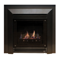
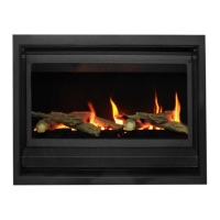
Introduces the Landscape as a ribbon burner space heater for Natural Gas and Propane.
Highlights cautions for placement, high operating temperatures, and child supervision.
Guides on choosing a safe, efficient location, considering clearances and traffic flow.
Warns against direct installation on combustible materials without protective panels.
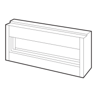
Provides detailed dimensional drawings and measurements for the Landscape 1000 main unit.
Shows dimensional information specific to the trim of the Landscape 1000 model.
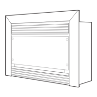
Provides detailed dimensional drawings and measurements for the Landscape 1600 main unit.
Displays dimensional information for the trim of the Landscape 1600 model.
Explains compatibility with horizontal or vertical cowls for balanced flue termination.
Table detailing flue dimensions for 90° and 45° bends for models 1000 and 1600.
Illustrates different flue components like bends and pipe lengths used in installation.
Instructs to construct an adequate base for the unit, ensuring it supports the fire's weight.
Details positioning the unit, fitting the flue, and connecting gas and power supplies.
Guides on building the frame around the fire, noting required clearances as shown on page 12.
Explains sheeting, plastering, and finishing the frame, ensuring proper material coverage.
Instructs to commission the fire according to the procedure outlined on page 14.
Provides a table with frameout dimensions (in mm) for models 1000 and 1600.
Lists required minimum clearances from floor, sides, top, flue outer, front, and back to combustibles.
Details mandatory clearances for vertical flue terminations from roof, air inlets, and structures.
Shows diagrammatic representation of horizontal and vertical termination clearances.
Guides on selecting appropriate locations for balanced flue terminations, avoiding obstructions.
Emphasizes maintaining flueing clearances and not modifying components for safe operation.
Lists essential tests for installers: gas leaks, pressure settings, and customer instruction.
Provides instructions and warnings for setting up decorative pebbles, avoiding burner cutouts.
Shows the arrangement for logset components on the 1600 model's burner logplate.
Illustrates the placement of logset components on the 1000 model's burner logplate.
Displays the individual log and coal components (labeled A-R) for setting up the fire.
Shows the initial placement of logset components (A, B, C, D, E) on the burner.
Illustrates the placement of additional logset components (F, G, H) in the second stage.
Depicts the arrangement of logset components (J, K) in the third step of the setup.
Shows the placement of logset components (P, F, G, K) in the fourth step of the setup.
Illustrates the placement of component L in the fifth step of the logset assembly.
Shows the final assembled log configuration, labeled N.
Shows the initial placement of logset components (A, B, C, D, E) on the burner for the 1600 model.
Illustrates the placement of components (M, H, P, Q, R, F, G) in the second stage of the 1600 logset setup.
Depicts the arrangement of logset components (J, K) in the third step of the 1600 logset assembly.
Shows the placement of logset components (K) in the fourth step of the 1600 logset assembly.
Illustrates the placement of component L in the fifth step of the 1600 logset assembly.
Shows the final assembled log configuration for the 1600 model, labeled N.
Step-by-step visual guide for disassembling the appliance for servicing (steps 1-7).
Continues the step-by-step visual guide for servicing (steps 8-9).
Details procedures after servicing, including reassembly and leak checks.
Lists critical safety checks required before operating the appliance after servicing.
Advises on annual inspections of the installation, flue system, and flame pattern.
Identifies the SIT 845 Sigma gas control valve as a component.
Identifies the SIT 579 electronic flame control device.
Lists the Millenium Thermostat Remote Control System as a part.
Details the SIT pilot assembly, including pilot, pilot tube, and burner tube.
Diagram showing the gas inlet, test pressure points, and adjustments.
Diagram showing the gas outlet and adjustments for high and low pressure.
Illustrates the Balanced Flue system with termination points and clearances.
Defines the symbols (T, M, P) used in the flue termination diagrams.
Table detailing minimum clearances for flue terminals based on appliance input and termination type.
Provides clarifications regarding measurements and specific regulations for flue terminals.
Introduces remote control operation, RF transmission, LCD display, and battery requirements.
Guides on optimal placement of the remote to ensure accurate room temperature readings.
Details default modes and fan behavior upon startup and shutdown.
Instructions on how to turn the thermostat on and off using the remote.
Explains the process for setting the current day and time on the remote.
Details how to adjust the hour setting on the remote.
Explains how to adjust the minute setting on the remote.
Guides on setting the current day of the week on the remote.
Explains operation in manual mode, allowing direct temperature adjustment.
Describes automatic mode, regulating temperature by programmed time and level.
Details how to temporarily adjust temperature while in automatic mode.
Introduces programming for setting daily temperature schedules with 4 periods.
Lists suggested time periods (morning, daytime, evening, night-time) for programming.
Instructions on how to initiate the programming mode on the thermostat.
Guides on selecting the specific day(s) for programming.
Explains how to set the start time for each programmed period.
Details how to set the desired temperature for each programmed period.
Provides the sequence to reset the thermostat to its factory default settings.
Instructions for pairing the thermostat with the control unit, with a caution.
Warns about thermostat behavior in Auto mode when room temperature drops and advises on extended absences.
Shows the Printed Circuit Board (PCB) layout and connections for the Landscape 1000 model.
Identifies the SIT Ignition Control unit and its connections.
Shows connections for the fan motor and modulating coil to the PCB.
Displays the Printed Circuit Board (PCB) layout and connections for the Landscape 1600 model.
Identifies the SIT Ignition Control unit and its connections for the 1600 model.
Shows connections for Fan Motor 1 and Fan Motor 2 to the PCB.
Illustrates the connection for the modulating coil.
Addresses issues where the remote is unresponsive, suggesting reprogramming or battery replacement.
Troubleshoots the fire cutting off and failing to relight, advising to cool down and contact manufacturer.
Addresses issues with the fan not operating, suggesting checking for overheat or electrical faults.
Troubleshoots low flame appearance, indicating potential pressure setting issues.
States that all service and repairs must be done by an authorized agency.
Informs about the availability of spare parts and trim finishes from Real Flame Pty Ltd.
Provides contact details for the main office, factory, and showroom in Scoresby, VIC.
Lists contact details for Richmond, Dandenong, and Geelong showrooms in Victoria.
Lists contact details for Sydney and Miranda showrooms in New South Wales.
Provides contact details for the Adelaide, South Australia showroom.
Provides contact details for the Miton, Queensland showroom.
Provides contact details for the Perth, Western Australia showroom.
Provides contact details for the Fyshwick, ACT showroom.
| Brand | Real Flame |
|---|---|
| Model | LANDSCAPE BALANCED |
| Category | Heater |
| Language | English |