EasyManua.ls Logo

Realistic STA-115 - Page 16

Realistic STA-115
66 pages
Print Icon
To Next Page IconTo Next Page
To Previous Page IconTo Previous Page
Loading...
CONNECTION
REPAIR
ADJUSTMENT
R EPAIR
CHECK
(.
l.
l.
t
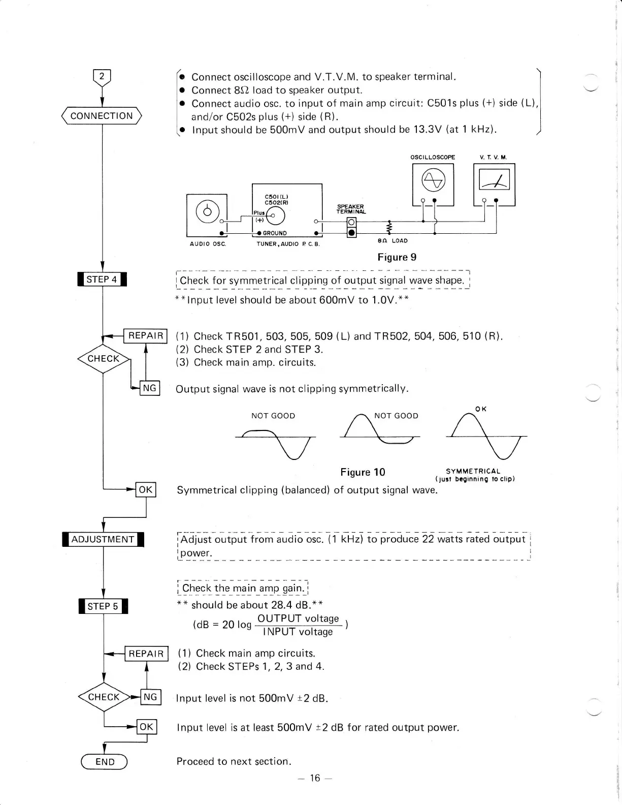
Connect
oscilloscope and
V.T.V.M. to speaker
terminal.
'l
Connect
8O
load to
speaker
output.
]
Connect
audio osc.
to
input of
main
amp
circuit: C501s
plus
(+)
side
(L),1
and/or
C502s
plus
(+)
side
(R)
|
lnput should be 500mV
and output should
be 13.3V
(at
1
kHz)
)
OSCILLOSCOPE VIV.M
auDro osc.
TUNER,AUDTO
PC.3
en LoAo
Figure 9
t--------------l
l-c_ry
9 L l"l 1yl]l.l
rl.3
l_c I
i
p
p
i n_s
_o
f
9 lt! lt :,! 1u L
y1:
$i
q g
_i
*
*
lnput
level
should be about 600mV
to
1.0V.*"
(1)
Check TR501, 503, 505, 509
(L)
and TR502,
504, 506, 510
(R),
(2)
Check
STEP 2
and
STEP
3.
(3)
Check
main
amp.
circuits.
Output
signal
wave is not
clipping
symmetrically.
NOT
GOOD
^v
Figure 10
Symmetrical
clipping
(balanced)
of output signal
iAJ;rit
"riprtlA,
*oio oiC.IItnri
SYMMETRICAL
(jusi
bcginninO
to clip)
WAVC.
to
produce
22 watts
rated
output
iQn* t,f"
".1i"
.*n_Sq.q,
"*
should
be about 28.4 dB.*"
OUTPUT voltaqe
(dB
=
2u
ros
rNpurr *rtE-')
(1)
Check
main
amp
circuits.
(2)
CheckSTEPs
1,2,3 and4.
lnput
level is not
500mV
l2
dB.
lnput level is
at
least 500mV
t2dB
for rated output
power.
Proceed
to next
section.
-16
(+)